Heat exchanger and method of producing

a technology of heat exchanger and heat exchanger, which is applied in the direction of reinforcing means, stationary conduit assemblies, lighting and heating apparatus, etc., can solve the problems of connection and holding forces that are not sufficient to withstand the increasing for

Inactive Publication Date: 2006-08-24
MODINE MFG CO
View PDF8 Cites 44 Cited by
  • Summary
  • Abstract
  • Description
  • Claims
  • Application Information

AI Technical Summary

Problems solved by technology

However, it has been found that, in such structures, the reduction in materials (and related reduction in sheet thickness) can result in a heat exchanger in which the connection and holding forces may not be sufficient to withstand the increasing pressures and other loads to which the heat exchanger may be subjected.

Method used


Image

  • Heat exchanger and method of producing
  • Heat exchanger and method of producing
  • Heat exchanger and method of producing

Examples


Embodiment Construction

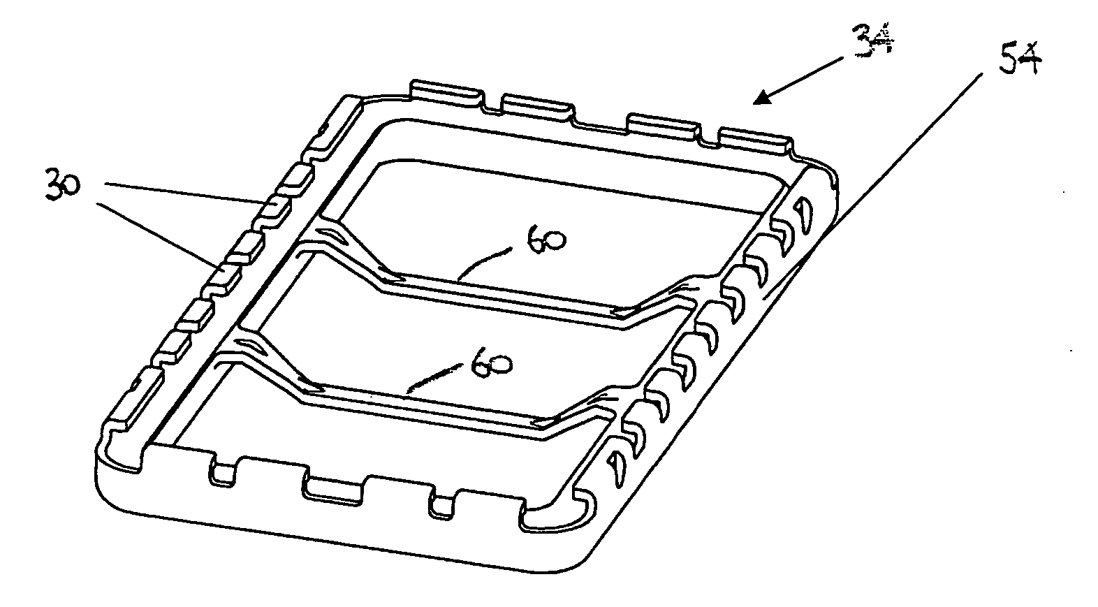
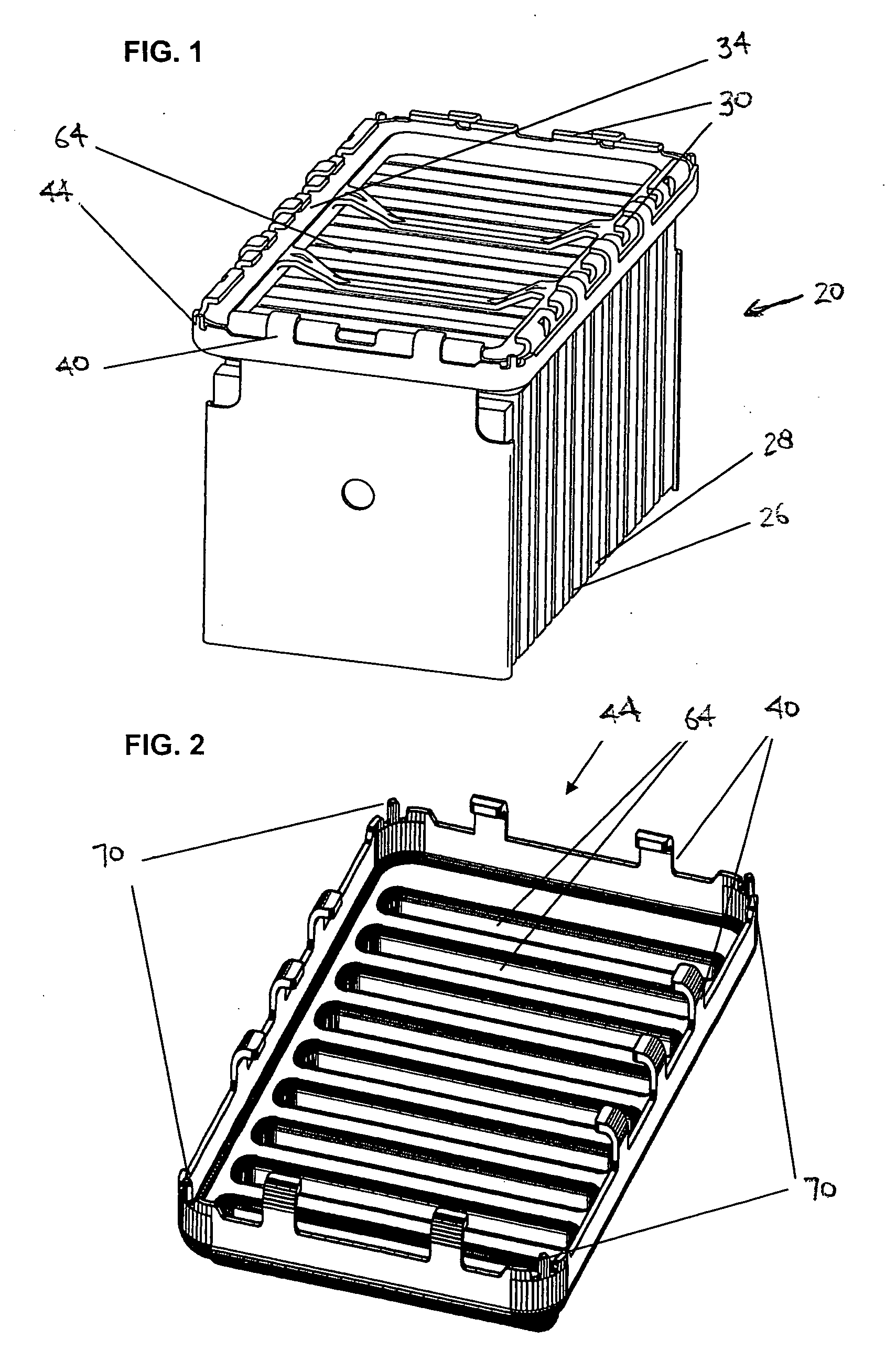
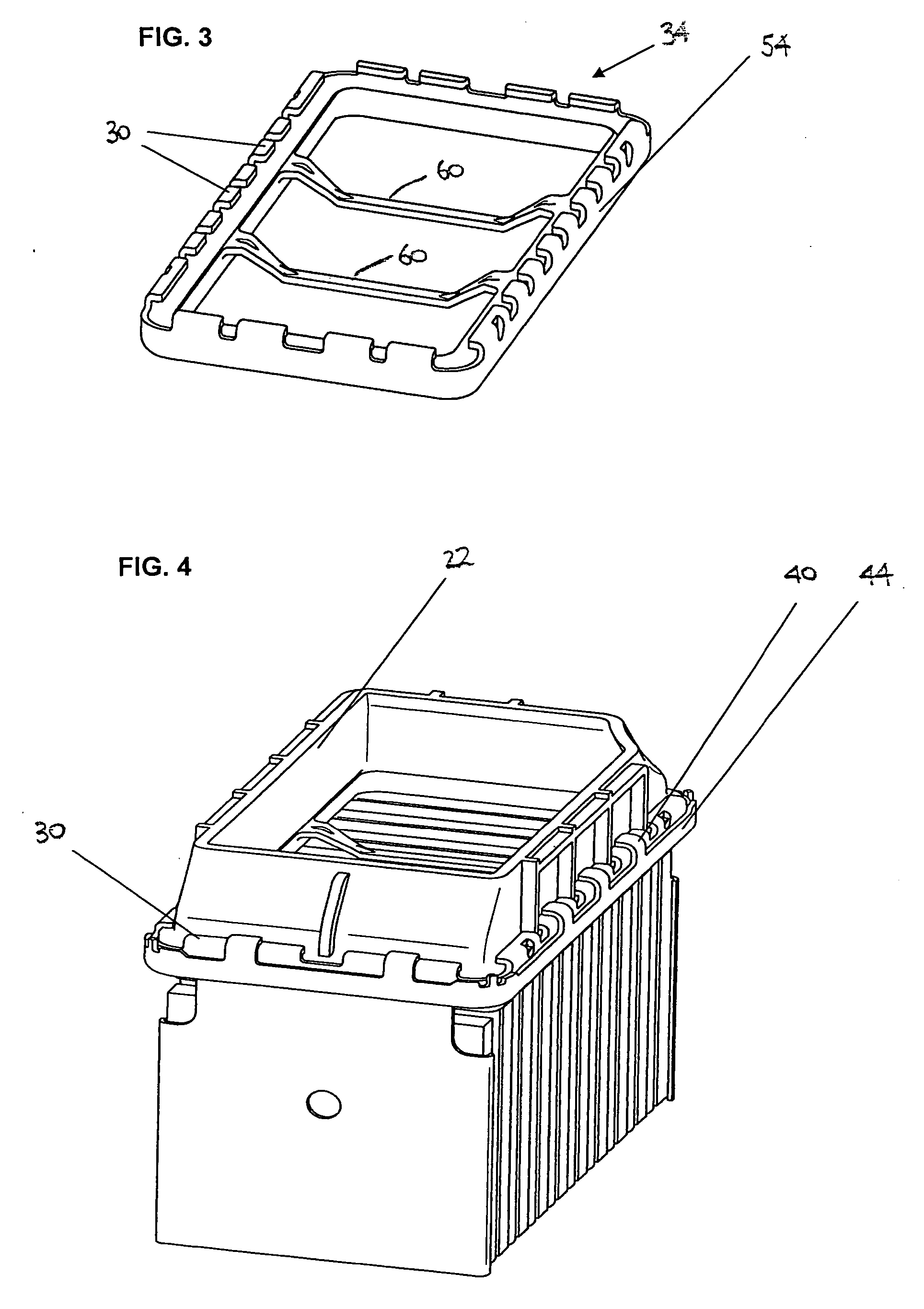
[0026] The present invention relates to a heat exchanger 20, for example, a charge air cooler or a coolant radiator, situated in a vehicle. For simplicity of illustration, the collecting tank 22 on only one side of the heat exchanger 20 is illustrated, though it should be understood that the other side may be identical at least in terms of the design of interest here. As is understood by those skilled in the art, cooling air usually flows through heat exchanger ribs 26, for example corrugated ribs, removing heat from the other medium which flows in tubes 28 via a collecting tank 22. As is understood by those skilled in the art, the ribs 26 and tubes 28 may be advantageously assembled to form a heat exchanger core during assembly of the heat exchanger 20

[0027] The heat exchanger 20 depicted in FIG. 1 is situated, in principle, in the state in which it is present after leaving a soldering furnace. In this condition, the connection edge 30 on the intermediate plate 34 and the connectio...


PUM

PropertyMeasurementUnit
weightaaaaaaaaaa
depthsaaaaaaaaaa
thicknessaaaaaaaaaa

Abstract

A heat exchanger including a collecting tank having an outwardly extending flange around an edge, a tube plate having a connection edge, tubes having ends extending into openings in the tube plate, and an intermediate plate having an edge lying against the connection edge of the tube plate. The connection edges of the intermediate plate and the tube plate are both mechanically connected to the flange of the collecting tank. Pins in the corners of one of the tube plate and the intermediate plate secure the tube plate and intermediate plate together. The connection edge of the plates include protrusions bendable onto the edge flange of the collecting tank.

Description

CROSS REFERENCE TO RELATED APPLICATION(S) [0001] Not applicable. STATEMENT REGARDING FEDERALLY SPONSORED RESEARCH OR DEVELOPMENT [0002] Not applicable. REFERENCE TO A MICROFICHE APPENDIX [0003] Not applicable. TECHNICAL FIELD [0004] The present invention relates to heat exchangers, and more particularly to heat exchangers having tubes secured to a tube plate connected along its edge to a collecting tank, and a method of producing such heat exchanger. BACKGROUND OF THE INVENTION AND TECHNICAL PROBLEMS POSED BY THE PRIOR ART [0005] Heat exchangers having tubes and ribs forming a core, in which a first medium (e.g., coolant) flows through the tubes and a second medium (e.g., environmental air) passes over the ribs for heat exchange between the two media are well known. Also well known are the use of collecting tanks with such cores, where the collecting tanks are secured to the ends of the tubes to distribute medium flow to the tubes (at the inlet end) and collect medium from the tubes...

Claims


Application Information

Patent Timeline
Patent Type & Authority Applications(United States)
IPC IPC(8): F28F9/02
CPCF28D1/05366F28F9/0224Y10T29/49389F28F2225/08F28F9/0229F28F2265/32F28F2275/122
Inventor BROST, VIKTORKASINGER, RAINERBAZIKA, DENIS
Owner MODINE MFG CO
Why Eureka
Try Eureka