Door lock apparatus for a vehicle

Active Publication Date: 2006-08-24
AISIN SEIKI KK
View PDF9 Cites 20 Cited by
  • Summary
  • Abstract
  • Description
  • Claims
  • Application Information

AI Technical Summary

Problems solved by technology

As a result, a door opening operation is disabled.
Those operations, however, may on occasions appear unfavorable.
However, an assembling process of the lock operation lever to

Method used


Image

  • Door lock apparatus for a vehicle
  • Door lock apparatus for a vehicle
  • Door lock apparatus for a vehicle

Examples


Embodiment Construction

[0024] An embodiment of the present invention will be described hereinbelow in detail with reference to the accompanying drawings.

[0025] As illustrated in FIG. 10, a door lock apparatus 1 according to an embodiment of the present invention is installed at a position of a door Y of a vehicle X, a position which faces a striker 300 of the vehicle X when the door Y is closed. A type of the door Y is not limited specifically and can be a hinge-type door, a slide-type door and so on. According to the embodiment of the present invention, the door lock apparatus 1 is mounted on a side door as the door Y by which an occupant can get on and off the vehicle X, as is apparent from FIG. 10. The door lock apparatus 1 can be however mounted on a trunk lid of a vehicle such as a hatchback-type vehicle. The door lock apparatus 1 is fixedly provided at an inner side of the vehicle X.

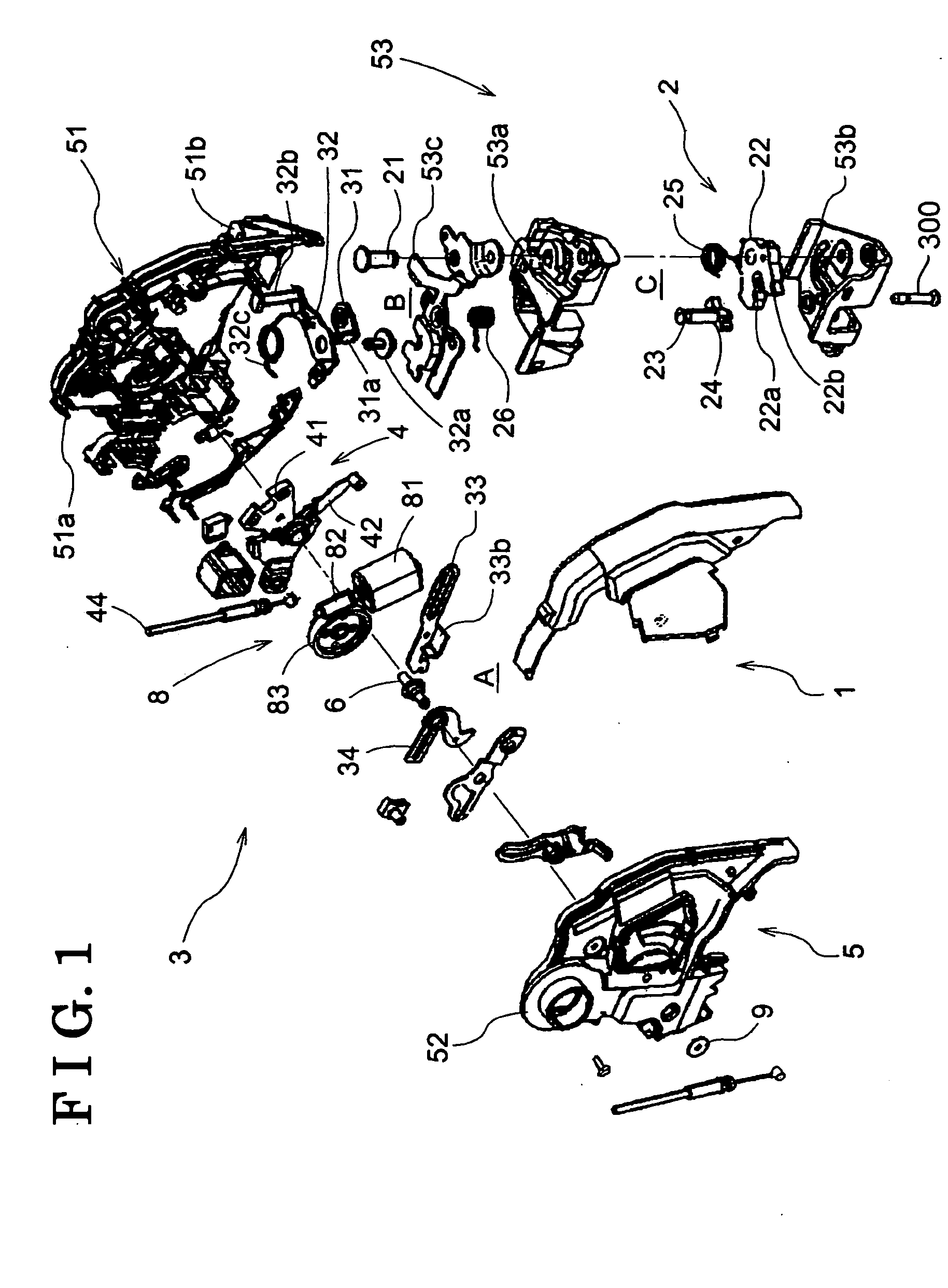
[0026] As illustrated in FIG. 1, the door lock apparatus 1 is mainly configured with a latch mechanism 2, a link mec...


PUM


Abstract

A door lock apparatus includes: a link member interposed between a latch mechanism and an open lever and selectively operated between an unlock position and a lock position, the unlock position in which an operation of the open lever is transmitted to the latch mechanism, and the lock position in which the operation is not transmitted to the latch mechanism; and a lock operation lever including an active lever and a sub lever, the sub lever configured to operate integrally with the active lever when the link member is switched to the lock position and to cooperate with the active lever via a biasing member when the link member is switched to the unlock position. The lock operation lever is an assembly containing the active lever, the sub lever and the biasing member.

Description

CROSS REFERENCE TO RELATED APPLICATIONS [0001] This application is based on and claims priority under 35 U.S.C. §119 with respect to Japanese Patent Application 2005-047499, filed on Feb. 23, 2005, and Japanese Patent Application 2005-089425, filed on Mar. 25, 2005 the entire content of which is incorporated herein by reference. FIELD OF THE INVENTION [0002] This invention generally relates to a door lock apparatus, which is configured to hold a door at a closed condition relative to a body and to lock the door. The door lock apparatus can be adapted to a vehicle. BACKGROUND [0003] Door lock apparatus have been conventionally known, which includes a latch mechanism, a lift lever, an open lever, a lock operation lever and a link member. For example, US2004036298A1 discloses such type of door lock apparatus. In this door lock apparatus, the latch mechanism can be adjusted to a vehicle door and can be engaged with, and disengaged from, a striker of a vehicle body. The lift lever is con...

Claims


Application Information

Patent Timeline
IPC IPC(8): E05C3/06
CPCE05B77/28E05B77/32E05B81/06E05B83/36E05B81/16E05B81/34Y10S292/23Y10T292/1047Y10T292/1082
Inventor FUKUNAGA, KATSUTOSHISUZUMURA, MAKOTOMURAMATSU, AKIRATANABE, SIGERUKUNIMATSU, YUKINOBUHIDAKA, KAZUHISA
Owner AISIN SEIKI KK
Why Eureka
Try Eureka