Air conditioner for vehicle

Inactive Publication Date: 2006-09-14
NIHON PLAST CO LTD
View PDF4 Cites 11 Cited by
  • Summary
  • Abstract
  • Description
  • Claims
  • Application Information

AI Technical Summary

Benefits of technology

[0003] However, cover 27 of the air conditioner of the above-described related art as conventionally proposed is adapted to simply hide the structural members within supply opening 23 which are located below cover 27. The conventional art does not c

Problems solved by technology

However, the installation space cannot be enlarged due to limitation on design to the interior of a vehicle compartment.

Method used


Image

  • Air conditioner for vehicle
  • Air conditioner for vehicle
  • Air conditioner for vehicle

Examples


Embodiment Construction

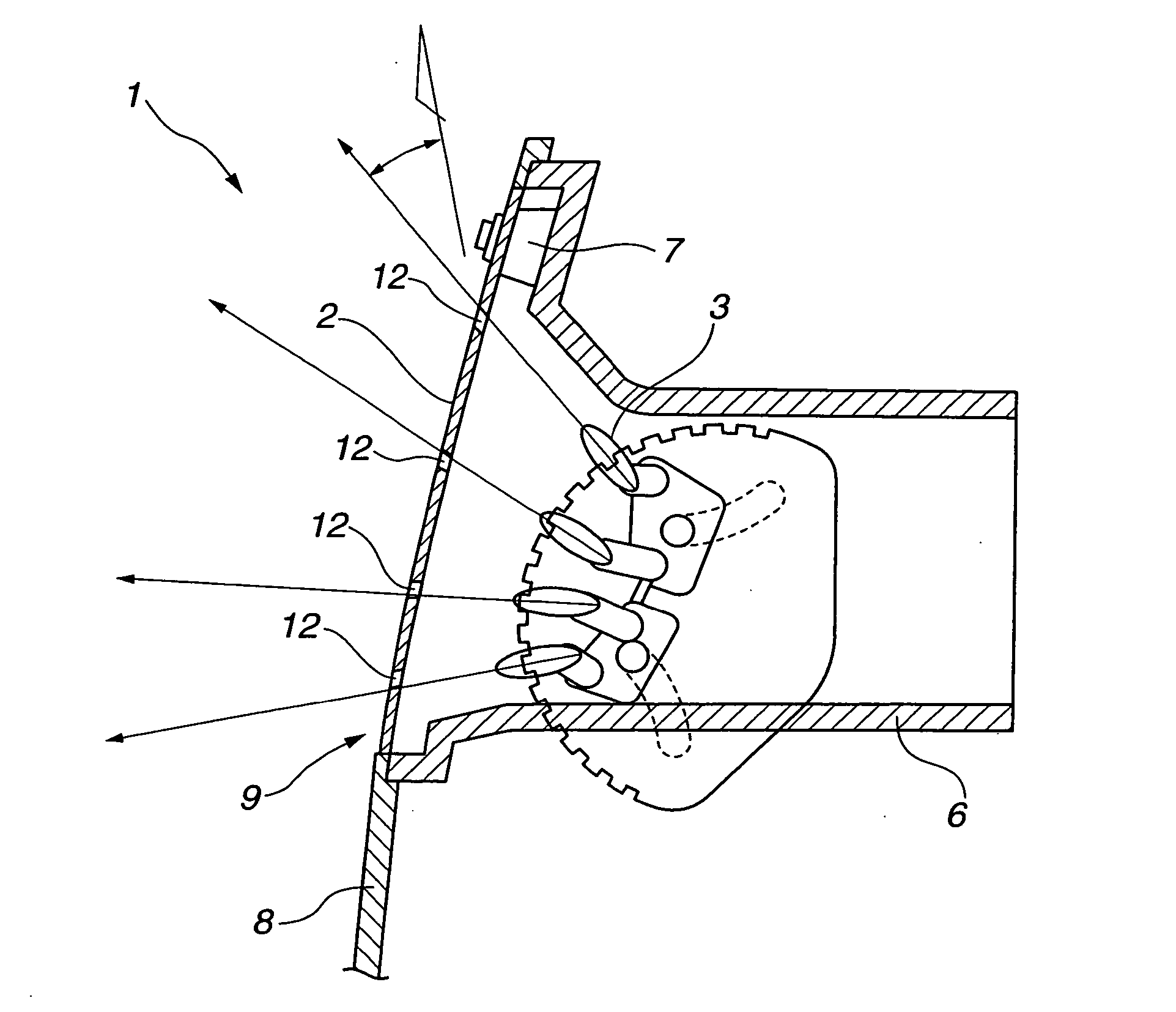
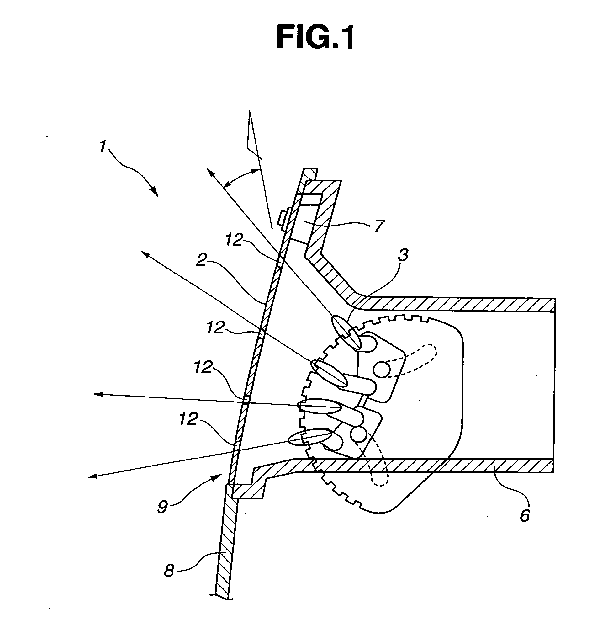
[0021] In the following, first to third embodiments of the present invention will be described in detail with reference to the accompanying drawings. Referring to FIGS. 1-2, an air conditioner for a vehicle, according to the first embodiment of the present invention is explained. As illustrated in FIG. 1, the air conditioner includes perforated panel 2, louver 3 and air conditioner casing 6 which are disposed inside instrument panel 8 of the vehicle. Air conditioner casing 6 is connected with a duct that supplies an air flow generated by a blower to air conditioner casing 6. Air conditioner casing 6 has supply opening 9 at an end portion thereof through which the air flow supplied via the duct is blown into a vehicle compartment. The end portion of air conditioner casing 6 is expanded toward an outside of air conditioner casing 6 so as to be formed into a generally sector-shape in section as shown in FIG. 1. Perforated panel 2 is mounted to the end portion of air conditioner casing ...


PUM


Abstract

A vehicular air conditioner including an air conditioner casing with a supply opening and a perforated panel with a plurality of vent holes, the perforated panel extending over the supply opening. The vent holes each extend through the perforated panel and each have an inlet opening exposed to an inside of the air conditioner casing, an outlet opening exposed to an interior of the vehicle compartment, and a nozzle length that extends from the inlet opening to the outlet opening and is within a range from 0.3 mm to 0.8 mm.

Description

BACKGROUND OF THE INVENTION [0001] The present invention relates to an air conditioner for a vehicle. [0002] In general, air conditioners for vehicles include louvers moveable to define a direction of an air flow that is blown from a supply opening into a vehicle compartment. Japanese Patent Application First Publication No. 2003-276429 describes an air conditioner for a vehicle as shown in FIG. 6. As shown in FIG. 6, the air conditioner is disposed within instrument panel 21 of the vehicle which is located rearward of front window panel 22. Front window panel 22 is rearward inclined in a fore-and-aft direction of the vehicle. Air conditioning duct 24 is disposed inside instrument panel 21 and connected to a periphery of supply opening 23 that is formed on instrument panel 21. An air is blown out from air conditioning duct 24 through supply opening 23. Cover 27 that is made of punching metal and adapted for ventilation is disposed over supply opening 23. Eight louvers 25a-25h are ar...

Claims


Application Information

Patent Timeline
IPC IPC(8): E04B7/00
CPCB60H1/3407B60H1/3421
Inventor KAMANO, YOSIFUMIYANAGIBASHI, SHINGONAKAMURA, TATSUHIKO
Owner NIHON PLAST CO LTD
Why Eureka
Try Eureka