Drive unit able to be applied to a vehicle provided with pedals

Inactive Publication Date: 2006-09-21
MR CIPRIANO RIZZETTO MESTRE
View PDF3 Cites 19 Cited by
  • Summary
  • Abstract
  • Description
  • Claims
  • Application Information

AI Technical Summary

Benefits of technology

[0013] Purpose of the invention is to achieve a drive unit able to be applied on a bicycle in order to assist and facilitate pedaling for the user, and wherein the drive unit is simple to construct, as compact in shape as possible and easy to use.
[0014] In accordance with this purpose, a drive unit according to the invention is able to be applied on a bicycle having at least a flywheel and a pair of pedals keyed onto a central shaft able to rotate around an axis. The drive unit comprises an electric motor able to be fed by electric feed means, motion transmission means able to connect the electric motor to the flywheel and a control unit able to detect, by means of corresponding sensor means, the speed of rotation of the central shaft in order to feed the electric motor proportionall

Problems solved by technology

The known drive unit, although very efficient and functional, has the disadvantage that in its entirety it is complex and articulated, and also bulky, due to the misaligned position of the motion transmission unit with respec

Method used


Image

  • Drive unit able to be applied to a vehicle provided with pedals
  • Drive unit able to be applied to a vehicle provided with pedals
  • Drive unit able to be applied to a vehicle provided with pedals

Examples


Example

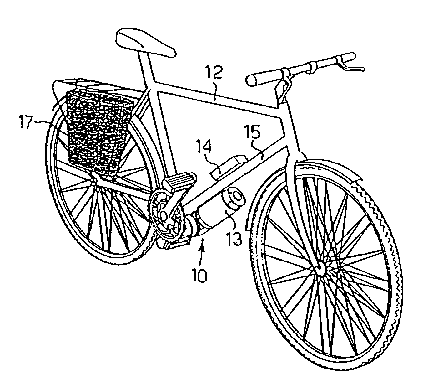
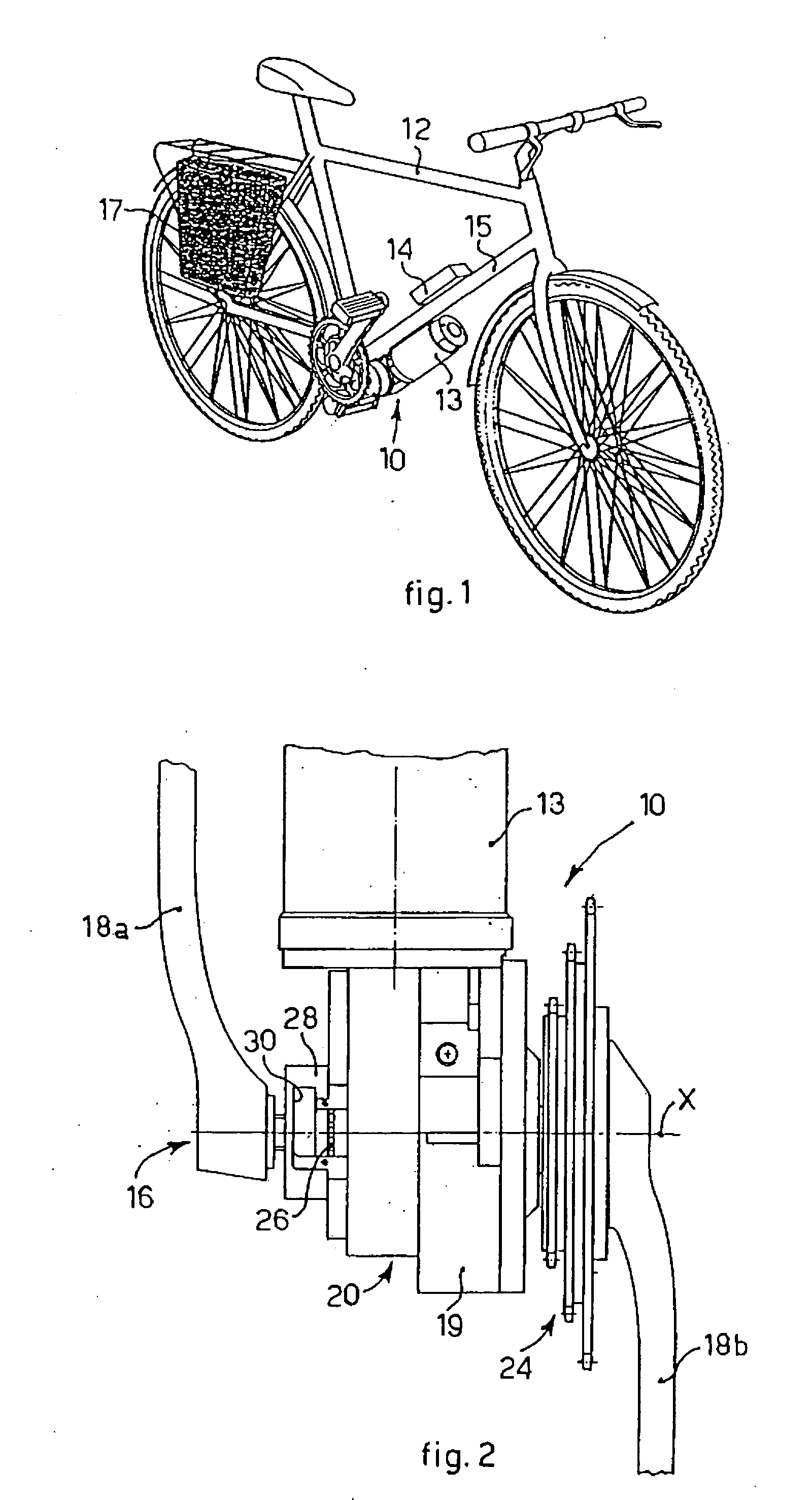
[0024] With reference to the attached drawings, a drive unit 10 is able to be assembled on a bicycle 12 in order to move it electrically, and is connected to a unit to actuate the motion 16, comprising a first pedal 18a and a second pedal 18b, keyed onto a central shaft 20 that rotates around an axis X.

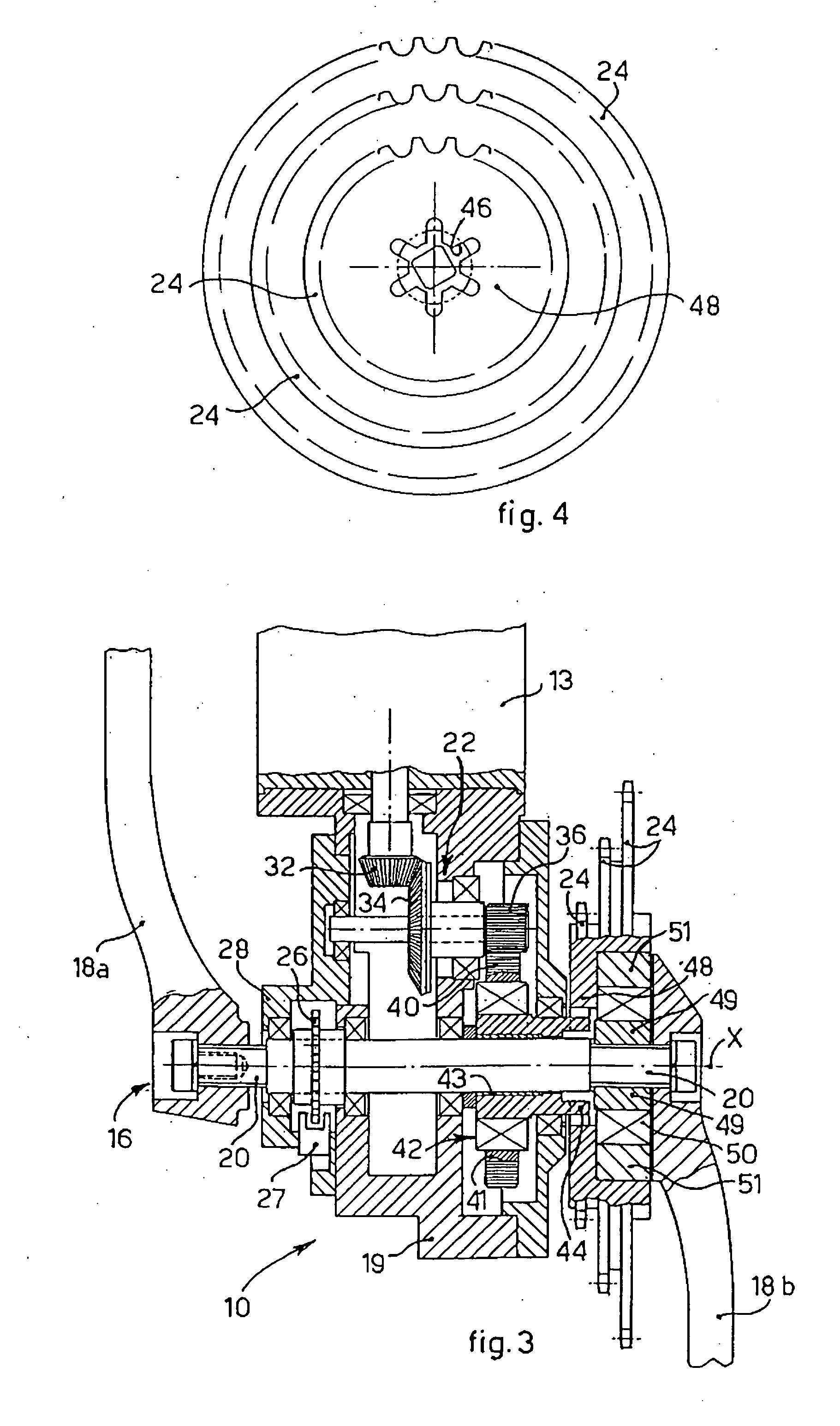
[0025] The drive unit 10 comprises, as essential parts, a feeder 17 comprising accumulators of a known type, an electric motor 13, which is connected to an electronic control unit 14, and a motion transmission unit 22 which is inserted into a box-like protective body 19, and is able to transmit motion from the electric motor 13 to a group of flywheels 24.

[0026] The box-like body 19, the pedals 18a and 18b and the flywheels 24 are made for example of a light alloy, such as aluminum alloy.

[0027] The motor 13 is applied on the lower side of the frame 15 of the bicycle 12, so it does not create any hindrance during pedaling, while the electronic control unit 14 can be arranged in any p...


PUM


Abstract

A drive unit able to be applied to a vehicle with pedals, like a bicycle, a tricycle or other, having at least a flywheel and a pair of pedals connected to a central shaft rotatable around a rotation axis. The drive unit comprises an electric motor, fed by an electric feed member, motion transmission members, which connect the electric motor to the flywheel, and a control unit that detects, by means of corresponding sensors, the speed of rotation of the central shaft connected to the pedals in order to feed, in proportion thereto, the electric motor. The drive unit also comprises a first free wheel which connects the motion transmission members to the flywheel, and a second free wheel that connects the central shaft to the flywheel. Both the free wheels are disposed coaxial with the flywheel so as to rotate around the rotation axis.

Description

FIELD OF THE INVENTION [0001] The present invention concerns a drive unit able to be applied to a vehicle provided with pedals, such as a bicycle, a tricycle, a four-wheeled cycle or suchlike, and also the vehicle provided with said drive unit. In the following text the term bicycle must therefore be taken to mean any vehicle provided with pedals, irrespective of the number of wheels. [0002] The drive unit according to the present invention is governed by the movement of the pedals and is able to automatically transmit motion, which is proportionate to said movement, to at least a toothed crown, or flywheel, of the bicycle. The motion is transmitted by means of very simple and at the same time functional mechanisms, so as to render pedaling as easy and comfortable as possible for the user. BACKGROUND OF THE INVENTION [0003] A drive unit is known, from the patent application EP-A-0968911, of which the present Applicant is proprietor, in the form of an assembly kit able to be applied ...

Claims


Application Information

Patent Timeline
IPC IPC(8): B62M9/04G05G1/30B62M6/55
CPCY10T74/2164B62M6/55
Inventor RIZZETTO, CIPRIANO
Owner MR CIPRIANO RIZZETTO MESTRE
Why Eureka
Try Eureka