Driving mechanism

Inactive Publication Date: 2006-10-26
FUJI PHOTO OPTICAL CO LTD
View PDF14 Cites 20 Cited by
  • Summary
  • Abstract
  • Description
  • Claims
  • Application Information

AI Technical Summary

Benefits of technology

[0011] The present invention has been made in view of the above problems, an object thereof is to provide a driving mechanism capable of reducing the effect of the resonance and providing an accurate and stable driving control by obtaining a more appropriate relationship between the resonance frequency and the driving frequency.

Problems solved by technology

Since the thus constituted actuator is fixed to a cabinet (or a support member) at one end surface of an electro-mechanical conversion element in the elongation and contraction direction, in association with vibration of the electro-mechanical conversion element, vibration generated on an actuator including a driving member is directly transmitted to the cabinet, thereby causing a problem that vibration has developed between the actuator and the cabinet.
Further, since the mechanism disclosed in Japanese Patent No. 3171187 is to make an active utilization of resonance, in any case, there is a problem that an adverse effect by resonance inside an actuator results in displacement of a driving member in a direction other than the elongating and contracting direction of a piezoelectric element.
Therefore, a driving force by the elongation and contraction of the piezoelectric element 1 is not accurately transmitted to a driven member 3, thereby making it difficult to accurately move the driven member 3 in the elongating and contracting direction of the piezoelectric element 1.
It is indispensable to make more rigid all the components including the cabinet, which results in a problem that a higher cost is needed in manufacturing the mechanism.
There is another problem that according to the conditional expression disclosed in the above Document, since the driving frequency can be established only in a relatively narrow range (in the range shown in Q of FIG. 6B), the resonance frequency is decreased to be deviated from the condition and adversely influenced by resonance, when the mechanism has defects or varies in quality.

Method used


Image

  • Driving mechanism
  • Driving mechanism
  • Driving mechanism

Examples


first embodiment

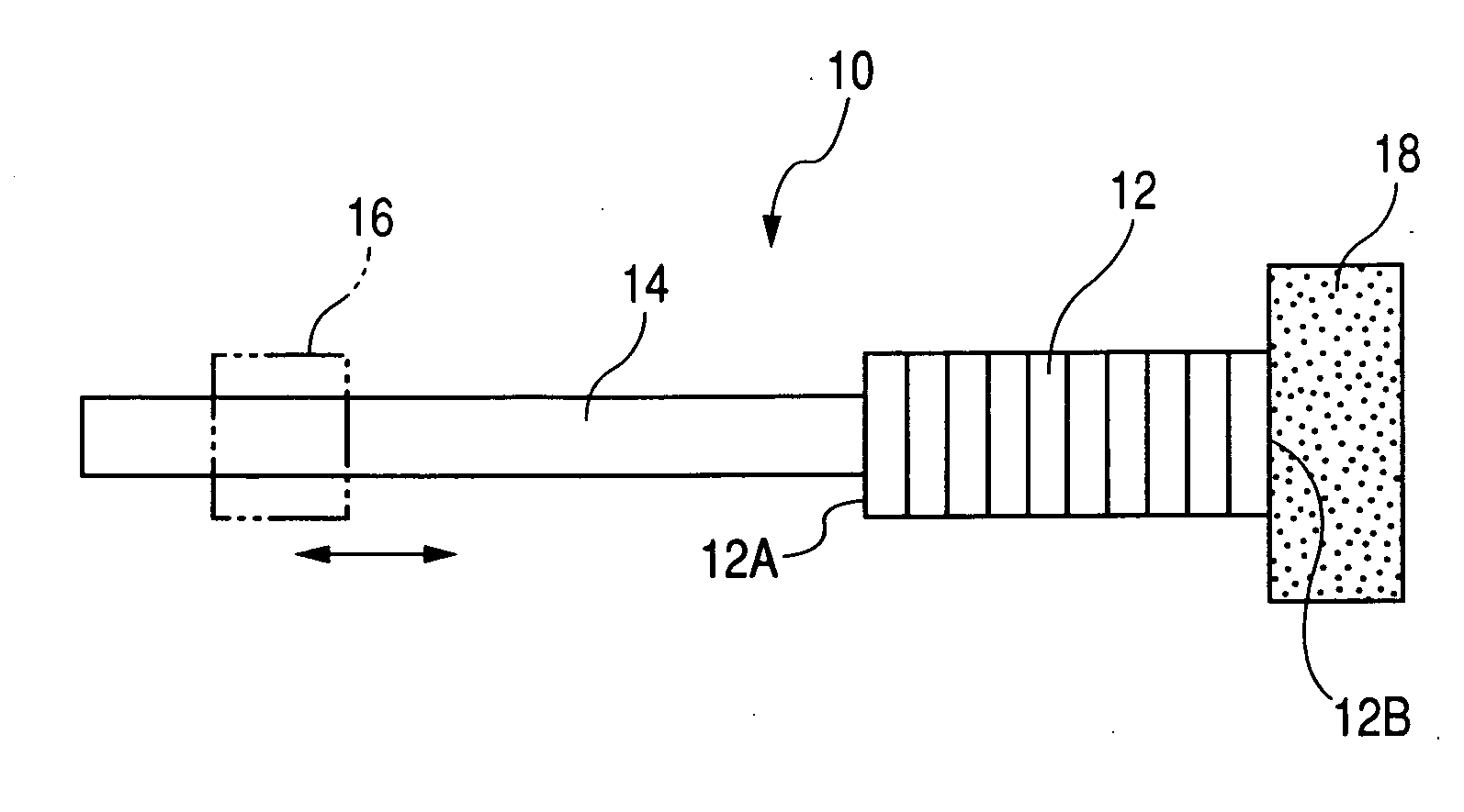
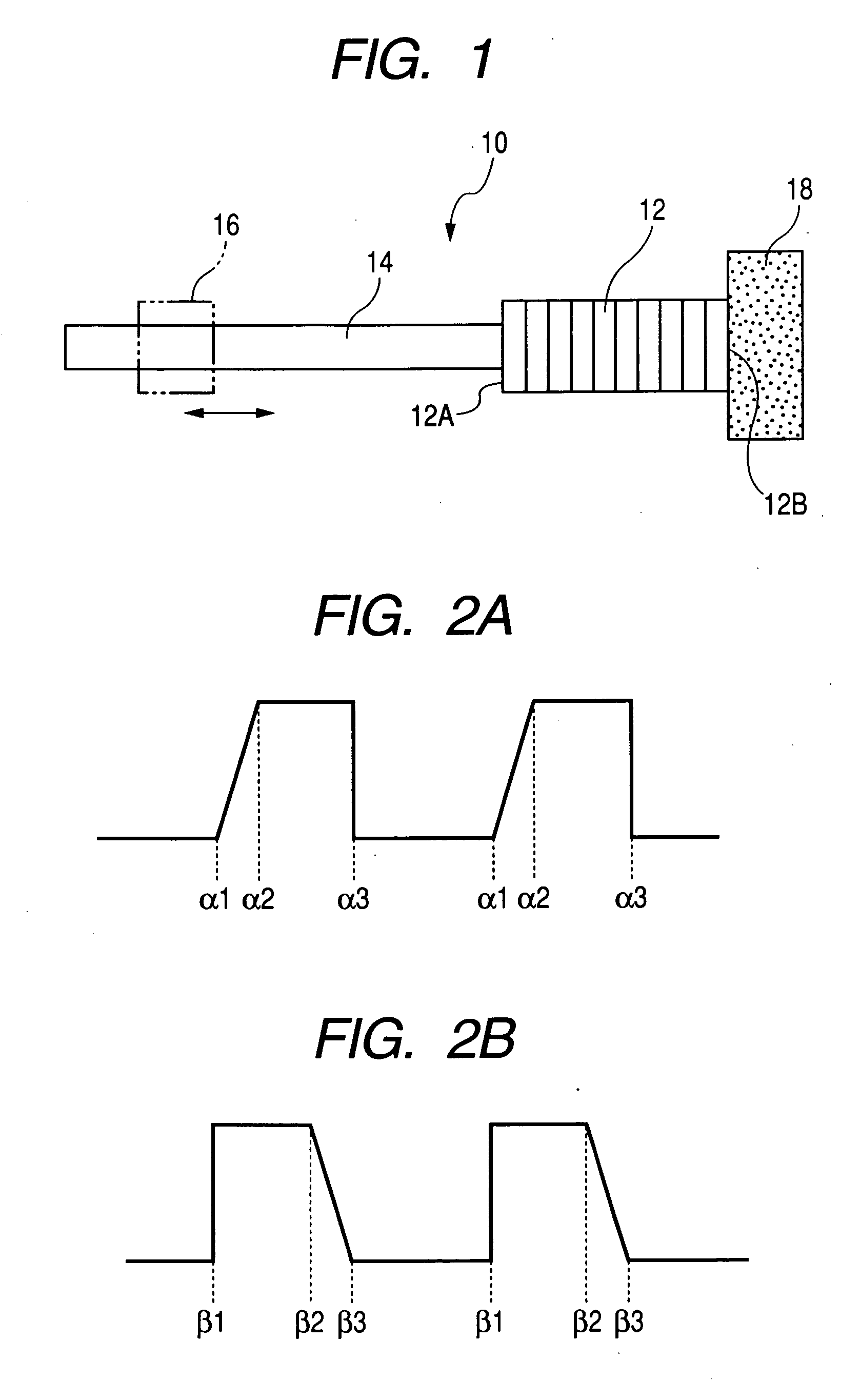
[0047]FIG. 1 is a plan view showing an actuator 10 of a driving mechanism 100 of a first embodiment in the present invention. As shown in FIG. 1, the actuator 10 is constituted by a piezoelectric element (corresponding to an electro-mechanical conversion element) 12, a driving member 14 and a weight member 18. The piezoelectric element 12 is laminated in the direction shown by the arrow and constituted so as to deform in a laminated direction (elongation and contraction) on application of voltage. Therefore, the piezoelectric element 12 is designed so that longer end surfaces 12A and 12B are displaced.

[0048] Of the end surfaces 12A and 12B of the piezoelectric element 12, to one end surface 12A is fastened a base end of the driving member 14. The driving member 14 is formed, for example, in a cylindrical shape, and its axis is arranged in the direction shown by the arrow (namely, in the elongating and contracting direction of the piezoelectric element). The driving member 14 is pref...

third embodiment

[0081] Next, an explanation will be made for a driving mechanism 300 of a third embodiment in the present invention with reference to FIG. 9.

[0082] As shown in FIG. 9, the driving mechanism 300 is different from the driving mechanism 200 in that a weight member 332 constituted by an elastic body such as rubber is adhered and fixed to the end surface 12B on the rear side of a piezoelectric element 12 and a surface opposite the piezoelectric element 12 in the weight member 332 is adhered and fixed to a body 20. The thus constituted mechanism is also able to secure a stable driving capacity constantly, as with the above embodiment.

fourth embodiment

[0083] Next, an explanation will be made for a driving mechanism 400 of a fourth embodiment in the present invention with reference to FIG. 10.

[0084] As shown in FIG. 10, the driving mechanism 400 is different from the driving mechanism 200 in that a weight member 418 made with a soft material is shaped into a thin plate form having a larger surface than the end surface 12B of a piezoelectric element 12, the piezoelectric element 12 is adhered and fixed at the center of the weight member 418, and both ends of the weight member 418 are adhered and fixed to a body 20. Since the end surface 12B at the rear end of the piezoelectric element 12 is supported to the body 20 by the thin-plate shaped weight member 418, the weight member 418 is deformed flexibly to cause displacement on the end surface 12B at the rear end of the piezoelectric element 12. In addition, since the weight member 418 is small in Young's modulus, the end surface 12B at the rear end of the piezoelectric element 12 is ...


PUM


Abstract

A driving mechanism comprises: (i) an actuator comprising: an electro-mechanical conversion element; a driving member which is connected to one end of the electro-mechanical conversion element and moves according to elongation or contraction of the electro-mechanical conversion element; and a weight member provided on the other end of the electro-mechanical conversion element; (ii) a driven member frictionally engaged with the driving member; and (iii) a driving circuit that drives the actuator, wherein the actuator allows the driven member to move along the driving member, and the driving circuit drives the electro-mechanical conversion element at a driving frequency f which gives f≧21 / 2·f0 when resonance frequency of a 1-freedom system is f0 in which the electro-mechanical conversion element and the driving member are designated as a mass and the weight member is designated as a spring, and driving frequency of the electro-mechanical conversion element is f.

Description

BACKGROUND OF THE INVENTION [0001] 1. Field of the Invention [0002] The present invention relates to a driving mechanism, a photographic mechanism in which an optical member is connected to the driving mechanism such as a small digital camera and a web camera and a cellular phone provided with the driving mechanism and the photographic mechanism. [0003] 2. Description of the Related Art [0004] An actuator in which an electro-mechanical conversion element such as a piezoelectric element is used is known as a driving mechanism for a lens used in digital cameras and the like. For example, as shown in the embodiments of Japanese Patent No. 3171187 or Japanese Patent No. 3171022, the actuator is, in general, constituted by an electro-mechanical conversion element and a driving member and fixed to a cabinet (or support member) on one end surface of the electro-mechanical conversion element in the elongation and contraction direction. A driving member is fastened to the other end surface o...

Claims


Application Information

Patent Timeline
IPC IPC(8): H01L41/00G02B7/08H02N2/00
CPCH02N2/067H02N2/025G01N3/02G01N3/08G01N2203/0423G01N2203/0017
Inventor MANABE, MITSUOICHIMIYA, TAKESHI
Owner FUJI PHOTO OPTICAL CO LTD
Why Eureka
Try Eureka