Powered band clamping under electrical control

Inactive Publication Date: 2002-09-19
BAND IT IDEX
View PDF5 Cites 55 Cited by
  • Summary
  • Abstract
  • Description
  • Claims
  • Application Information

AI Technical Summary

Benefits of technology

0014] Based on the foregoing summary, a number of salient features of the present invention are noted. Substantial electrical controls are provided for tightening, cutting, locking and clamp tail removal in connection with the operations for properly joining a band clamp to an object. Such greater electrical control includes the capabilities of providing various inputs and obtaining information by means of different visual and audio outputs. In conducting the tensioning of the band clamp, a strong grip of the band occurs using an openable gripper mechanism having a non-linear gripping surface contacted by the band portions. This design insures that no slipping of the band occurs during the tensioning thereof. A load cell is utilized for use in indicating the current actual tension being applied to the band clamp. The load cell is arranged with one or more gears of a gear mechanism to eliminate, or at least reduce,

Problems solved by technology

In the case of pneumatic or electrical tools used for such purposes, the power generated results in

Method used


Image

  • Powered band clamping under electrical control
  • Powered band clamping under electrical control
  • Powered band clamping under electrical control

Examples


Example

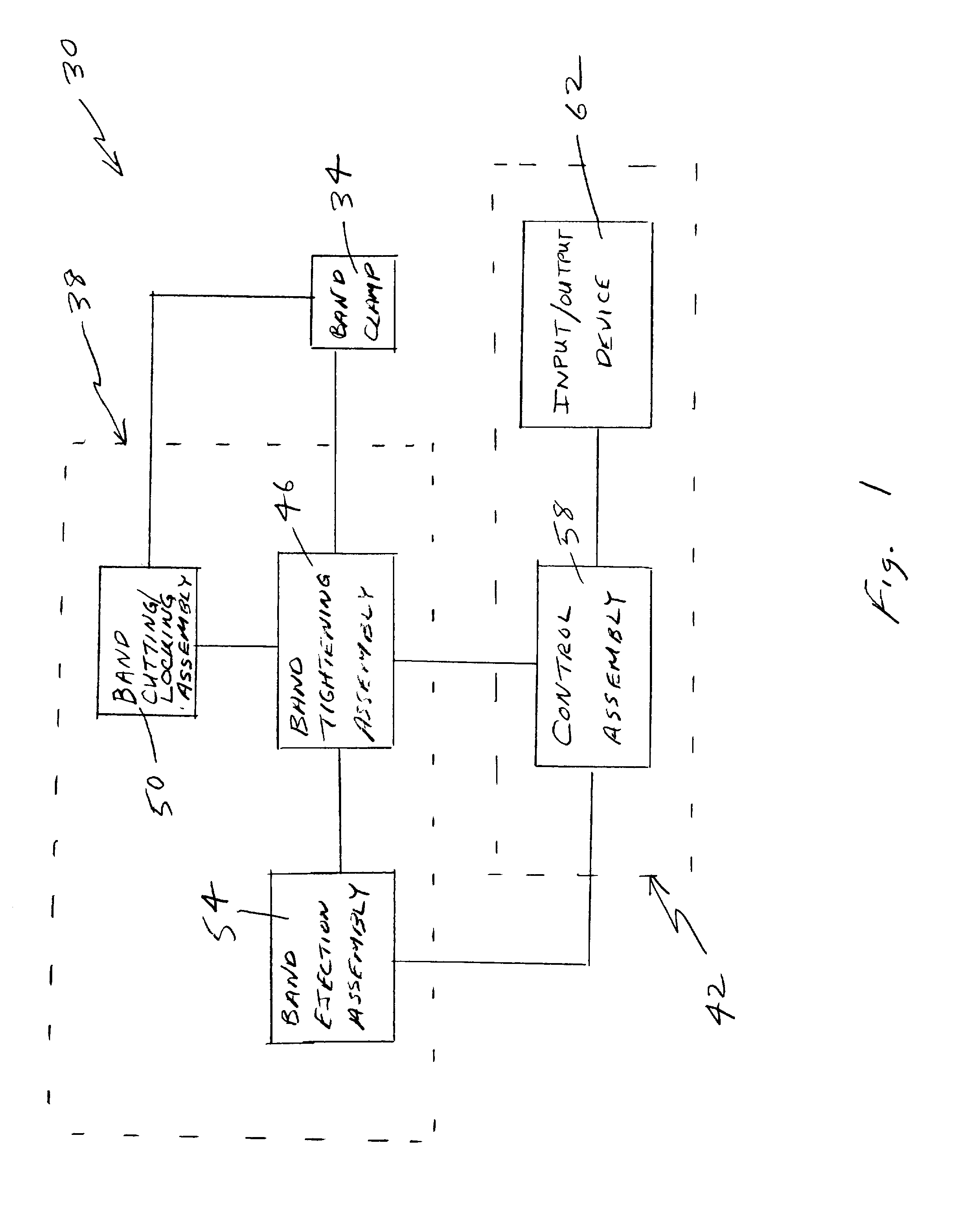
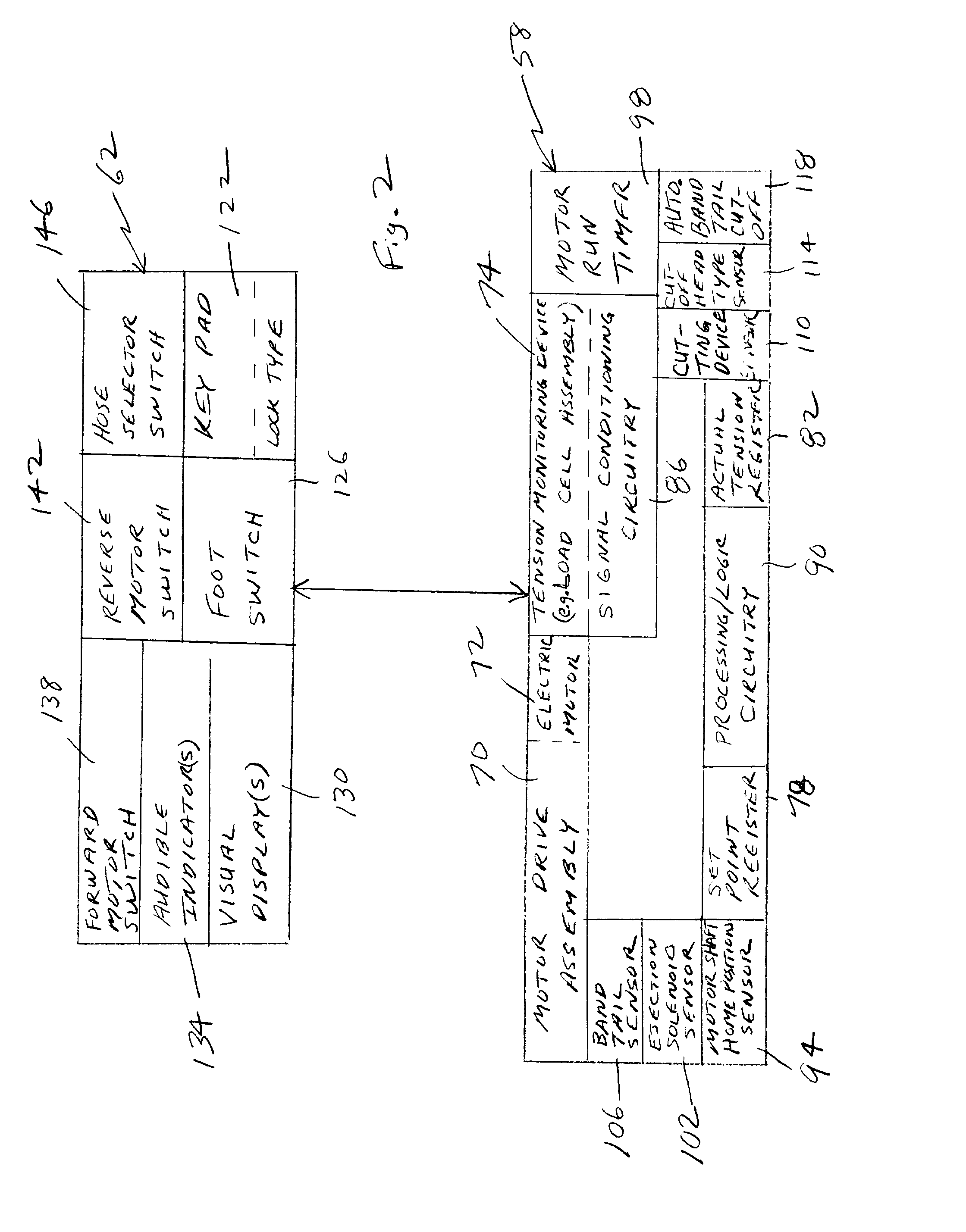
[0031] With reference to FIG. 1, an electrically controlled apparatus 30 is illustrated in a block or functional diagram that tightens a band clamp 34 to a desired tension based on an input from the operator or user. The apparatus includes a banding system 38 and a control system 42. The banding system is 38 generally involved with mechanical-related operations for providing the band clamp 34 about the object, such as a hose, that is being tightened. The control system 42 is generally involved with electrically controlling the banding system 38 so that it properly operates to tighten the band clamp 34 about the object.

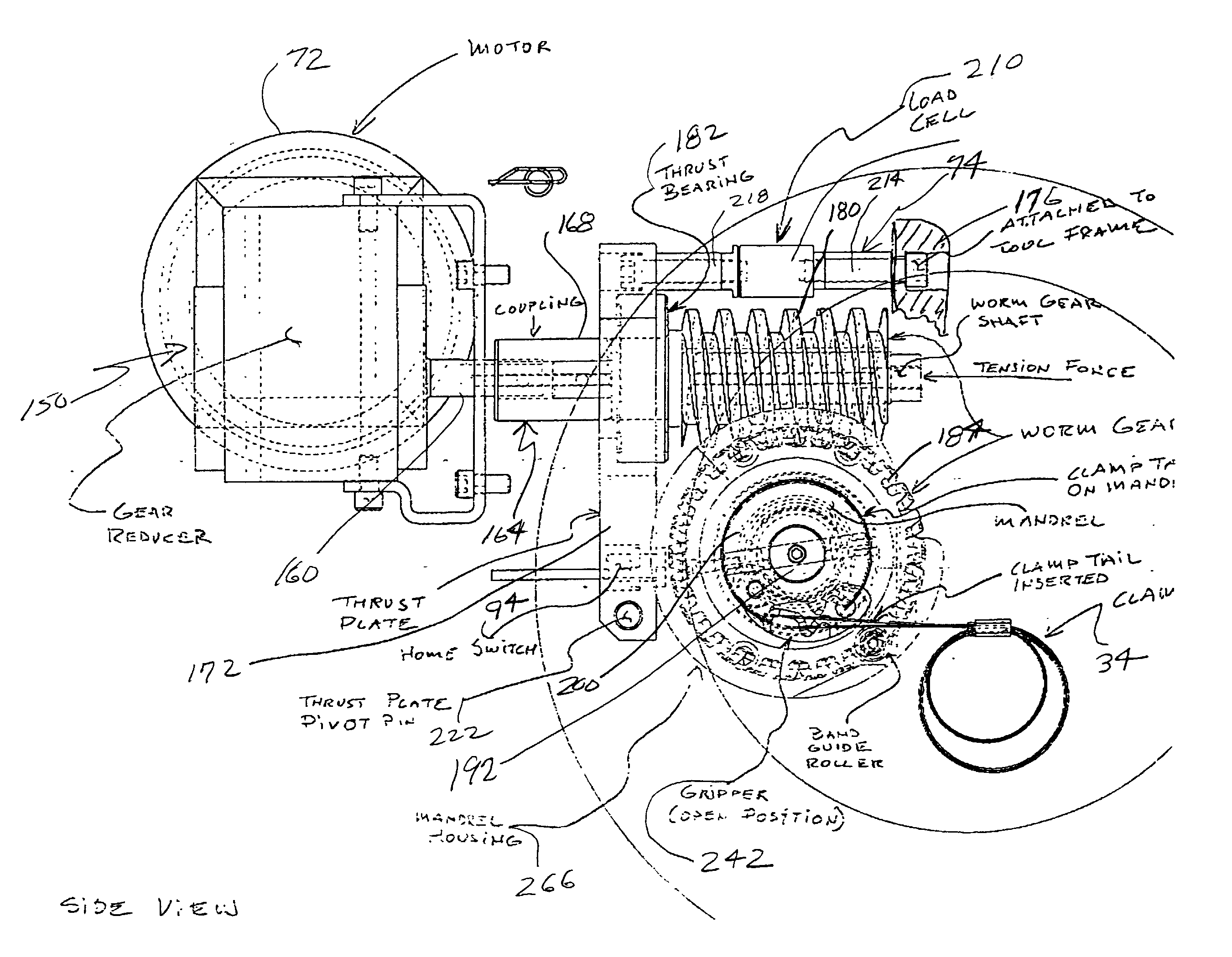
[0032] The banding system 38 includes a band tightening assembly 46 that receives a free end of the band clamp 34. When activated, the band tightening assembly 46 acts to tension or tighten the band clamp 34 by pulling thereon. Preferably, in conjunction with the pulling, the free end of the band clamp 34, together with portions integral therewith, are caused to be wra...


PUM

PropertyMeasurementUnit
Timeaaaaaaaaaa
Forceaaaaaaaaaa
Widthaaaaaaaaaa

Abstract

Tensioning of a band clamp about an object under electrical control is provided using a control system operably connected to a banding system. The banding system includes a number of mechanical components involved with tightening, cutting and locking the band clamp, as well as removing a tail portion thereof. The control system is operably connected to the assemblies of the banding system to automatically control at least certain operations associated with performing the functions of the apparatus. The banding system includes: a band tightening assembly including a mandrel about which the tail portion can be wrapped during the band tightening operation; a band cutting/locking assembly including a removable cutting device used in forming the lock and severing the tail portion; and a band ejection assembly used in removing the severed tail portion from the apparatus. The control system preferably includes a load cell that outputs an electrical signal related to the actual tension being applied to the band clamp during the tightening operation. The control system also includes an input/output device for receiving and outputting information related to the functions performed by the banding and control systems.

Description

FIELD OF THE INVENTION[0001] The present invention relates to clamping objects and, in particular, tensioning band clamps about hoses using electrical control.BACKGROUND OF THE INVENTION[0002] Many types of band clamps have been devised or advanced for use in clamping to objects, such as hoses, pipes, poles, cables and the like. Common band clamps can be provided to the user in preformed loops in which one or more generally circular wraps are already formed. Such a band clamp can be used with objects about which the one or more loops can be located and then subsequently tightened about the object to firmly hold the band clamp to the object. Common types of band clamps also include those having a free end that is initially wrapped about the object being clamped. Band clamps usually have a buckle or other locking-type element through which one or more wraps of the band are made. The buckle can be useful in creating a lock for the band clamp after it is properly tightened about the obj...

Claims


Application Information

Patent Timeline
IPC IPC(8): B23P19/08B65B13/22
CPCB23P19/084B23P19/086B65B13/027B65B13/22
Inventor CZEBATUL, PHILIP A.HINNEN, HANS R.MARELIN, MIKLOS B.
Owner BAND IT IDEX
Why Eureka
Try Eureka