
Phased array, a coherent source array, an antenna array and a system for controlling thereof

Active Publication Date: 2014-04-10
CITY UNIVERSITY OF HONG KONG
View PDF4 Cites 58 Cited by
  • Summary
  • Abstract
  • Description
  • Claims
  • Application Information

AI Technical Summary

Benefits of technology

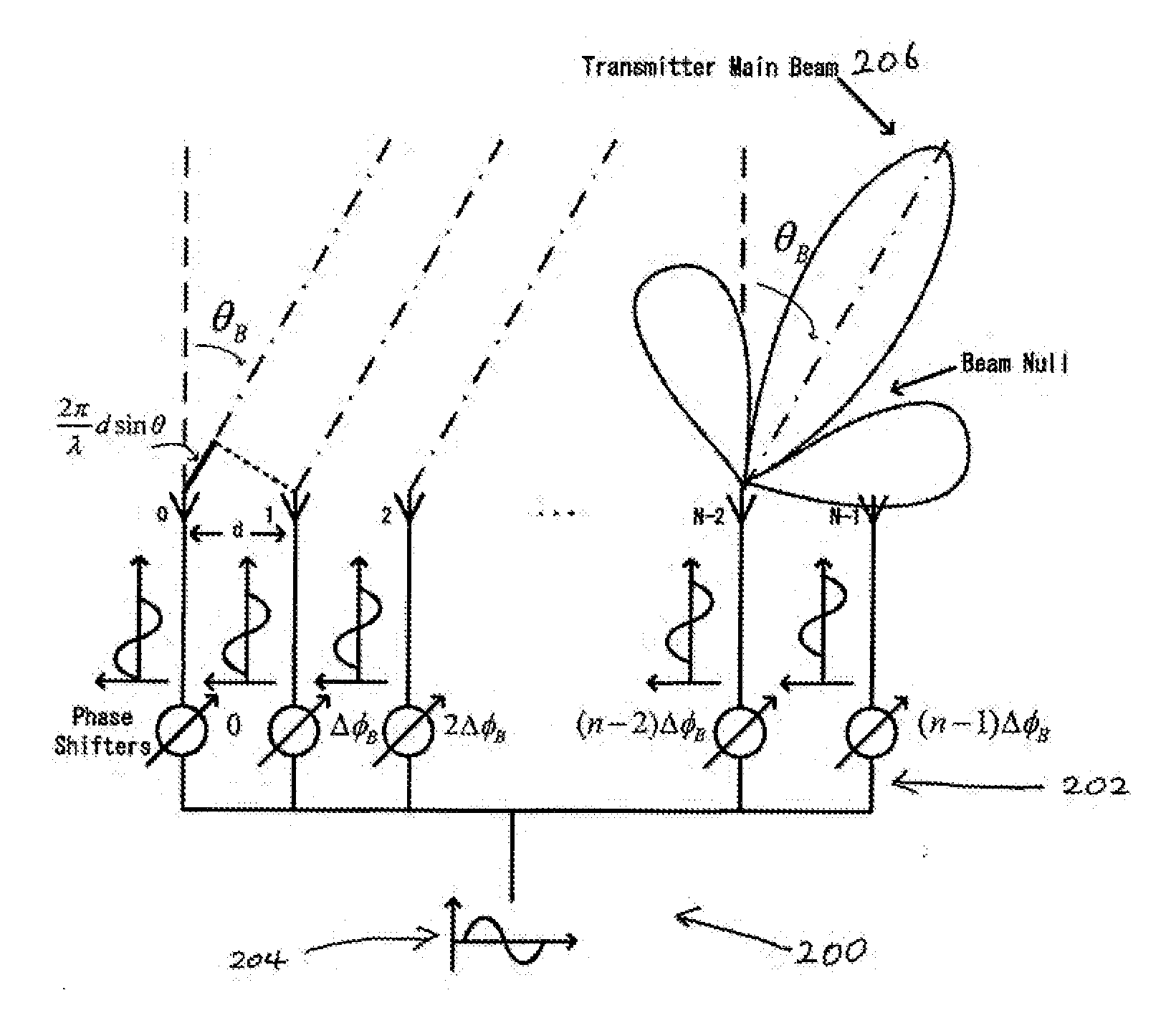
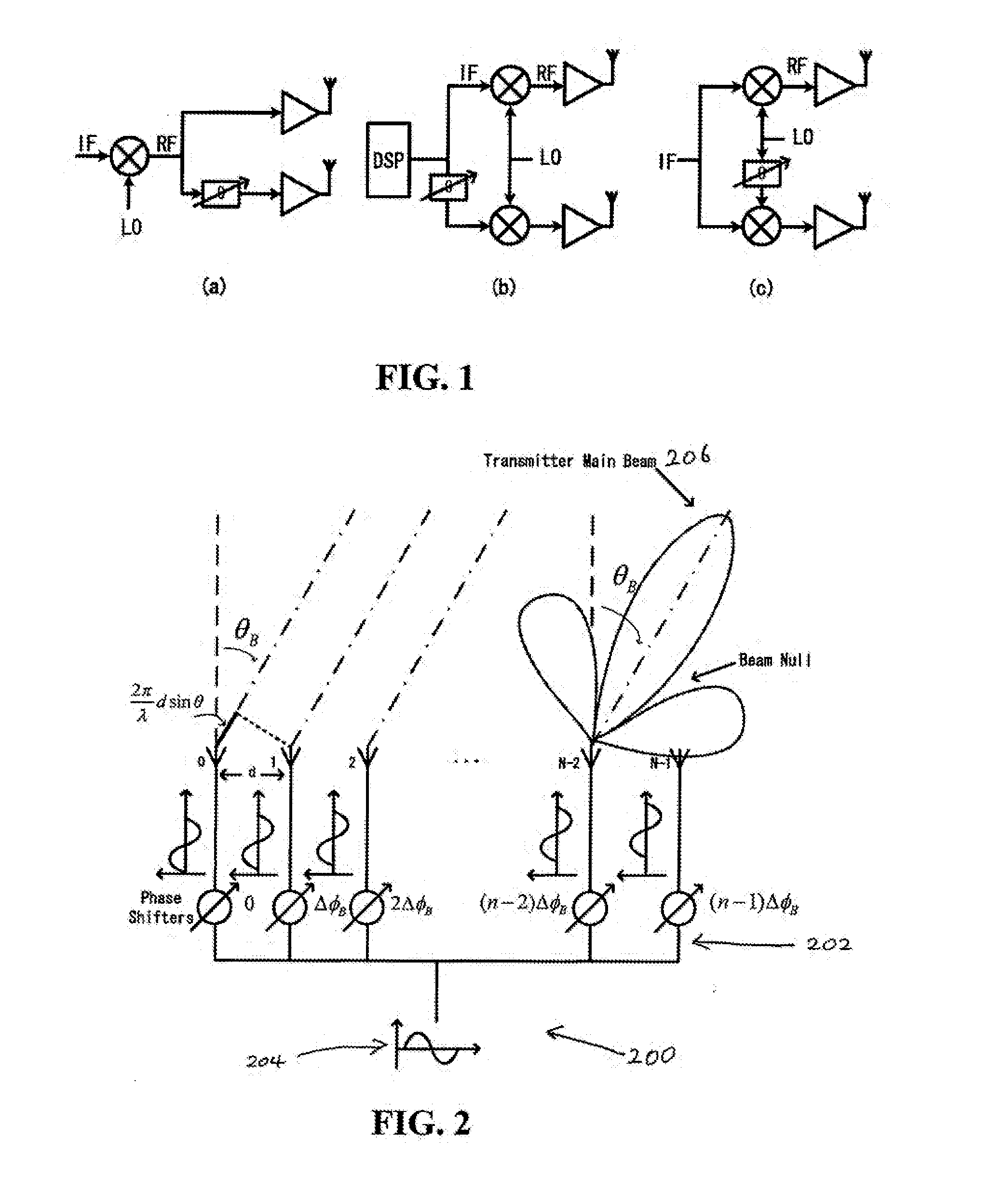
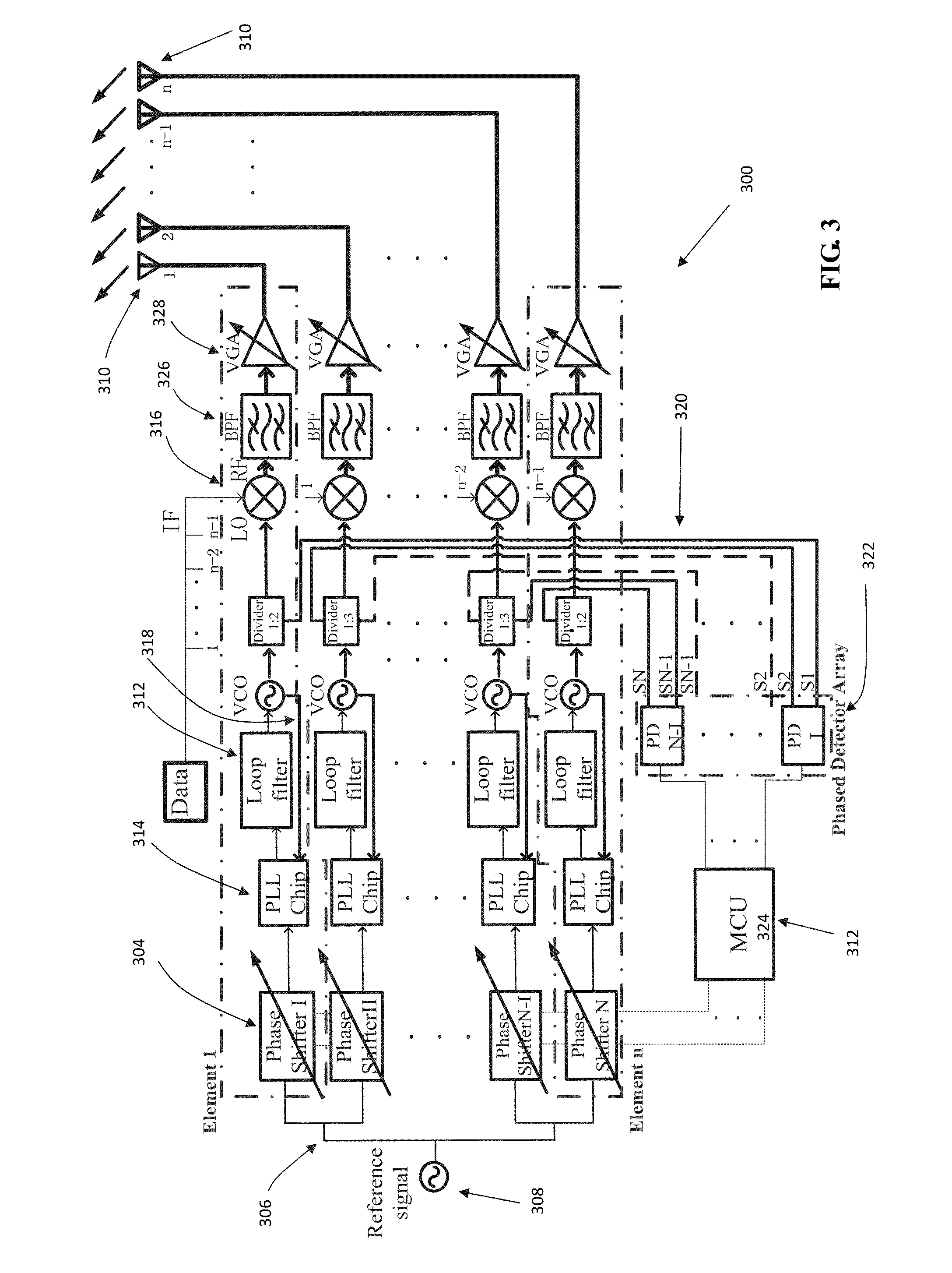
The patent describes a new technology for generating coherent sources for phased array applications. The technology uses low cost phase shifting circuits to shift the phase of the signal, which is then controlled using a low cost phase control module. This allows for real-time calibration on both frequency and phase, reducing the effect of components aging and environmental issues. The technology also allows for near-perfect LO beamforming performance and array pattern self-compensation realization. Overall, the technology offers practical advantages when implementing beamforming, compared to other techniques.

Problems solved by technology

Despite these attempts, operations of the multi-element antenna arrays are limited.
In part, this is due to the fact that components used to process and control the signals within each element are affected by aging and environmental factors during their operation and thus causes problematic processing and control of signals to perform a specific task successfully.

Method used


Image

  • Phased array, a coherent source array, an antenna array and a system for controlling thereof
  • Phased array, a coherent source array, an antenna array and a system for controlling thereof
  • Phased array, a coherent source array, an antenna array and a system for controlling thereof

Examples


example experimental

Results

[0094]In this embodiment, the phased transmitting array has four elements and it is implemented using electronic components mounted on a FR4 printed circuit boards (PCBs) with a dielectric constant εr=4.6 and height h=1.6 mm . The phased transmitter array is connected to a 4×1 dual-polarized magneto-electric (ME) dipole antenna array with odd ports fed. The block diagram of the far-field array measurement in anechoic chamber setup is shown in FIG. 11. A laptop works as the positioner controller, which is used to vary the phased array steering angle and feeding power. A signal generator (SMU200A) provides the baseband signal as IF signal to the phased array. After powered up by a power supply with a 6V DC voltage, the phased-array transmits the signal, which can be received by a standard gain horn and then be recorded by a spectrum analyzer (E4448A). A photograph of an embodiment of a 4×1 phased transmitting array measurement in anechoic chamber is displayed in FIG. 12.

[0095]A...


PUM


Abstract

A system for controlling a multi-element antenna array comprising a plurality of elements each arranged to receive a signal from a signal source, wherein each of the plurality of elements includes a frequency locking module arranged to lock the frequency of the signal received by each of the elements, and, a phase control module being in communication with each of the frequency locking modules to control the phase of the signal received by each of the elements.

Description

CROSS-REFERENCE TO RELATED APPLICATIONS[0001]The present application claims the benefit of U.S. Provisional Patent Application No. 61 / 692,917, filed Aug. 24, 2012.TECHNICAL FIELD[0002]This invention relates to a system for controlling an antenna array, and particularly, although not exclusively, to a system arranged to control a multi-element antenna array, a phased array or a coherent source array with a dual phase-locked loop infrastructure.BACKGROUND[0003]Multi-element antennas are antennas which have multiple radiating elements which are each arranged to radiate a signal. These antennas can be controlled to electronically steer a signal without a physical adjustment to the radiating elements. In recent times, attempts have been made by engineers and researchers to process and control the signals of each element, such as by phase and amplitude controlling through high frequency components or DSP controlling at baseband, so that the multi-element antenna array is able to perform v...

Claims


Application Information

Patent Timeline
IPC IPC(8): H01Q3/34
CPCH01Q3/34H03L7/23
Inventor XUE, QUANTANG, CHENGCHENG
Owner CITY UNIVERSITY OF HONG KONG
Learn More