Reagent cartridge

Inactive Publication Date: 2006-11-02
IK & PP LOGISTICS EQUIP CORP
View PDF2 Cites 8 Cited by
  • Summary
  • Abstract
  • Description
  • Claims
  • Application Information

AI Technical Summary

Benefits of technology

[0007] When one reagent contained inside one of the reagent compartments is exhausted, a user can replace the empty reagent compartment simply and conveniently.

Problems solved by technology

Thus, the way for using the conventional is environmentally unfriendly, and surplus reagents contained in the compartments are also discarded.
Further, when the conventional reagent cartridge is used, the caps mounted on the collars must be opened individually, whereby the way of using the reagent cartridge is inconvenient.

Method used


Image

  • Reagent cartridge
  • Reagent cartridge
  • Reagent cartridge

Examples


Embodiment Construction

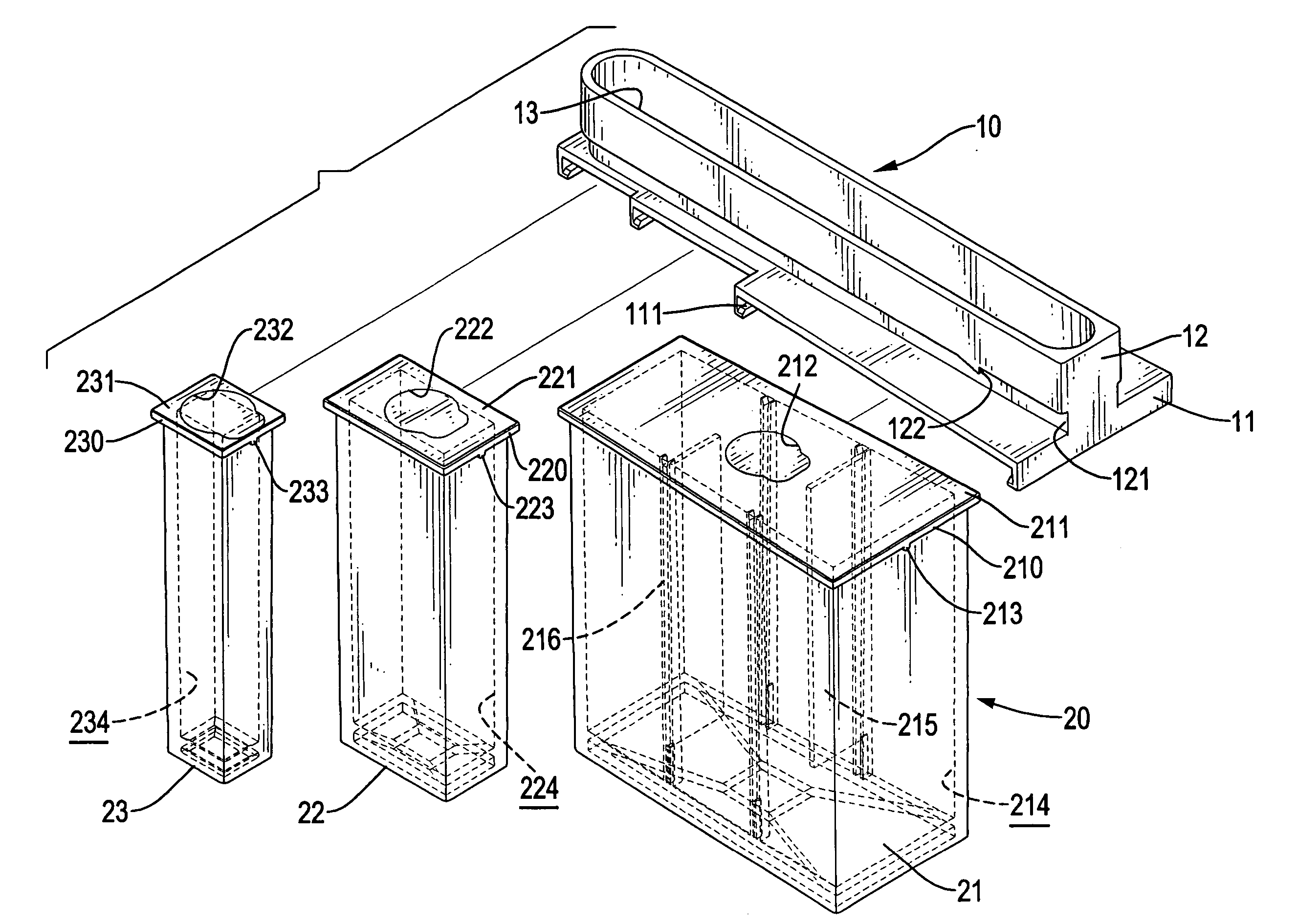
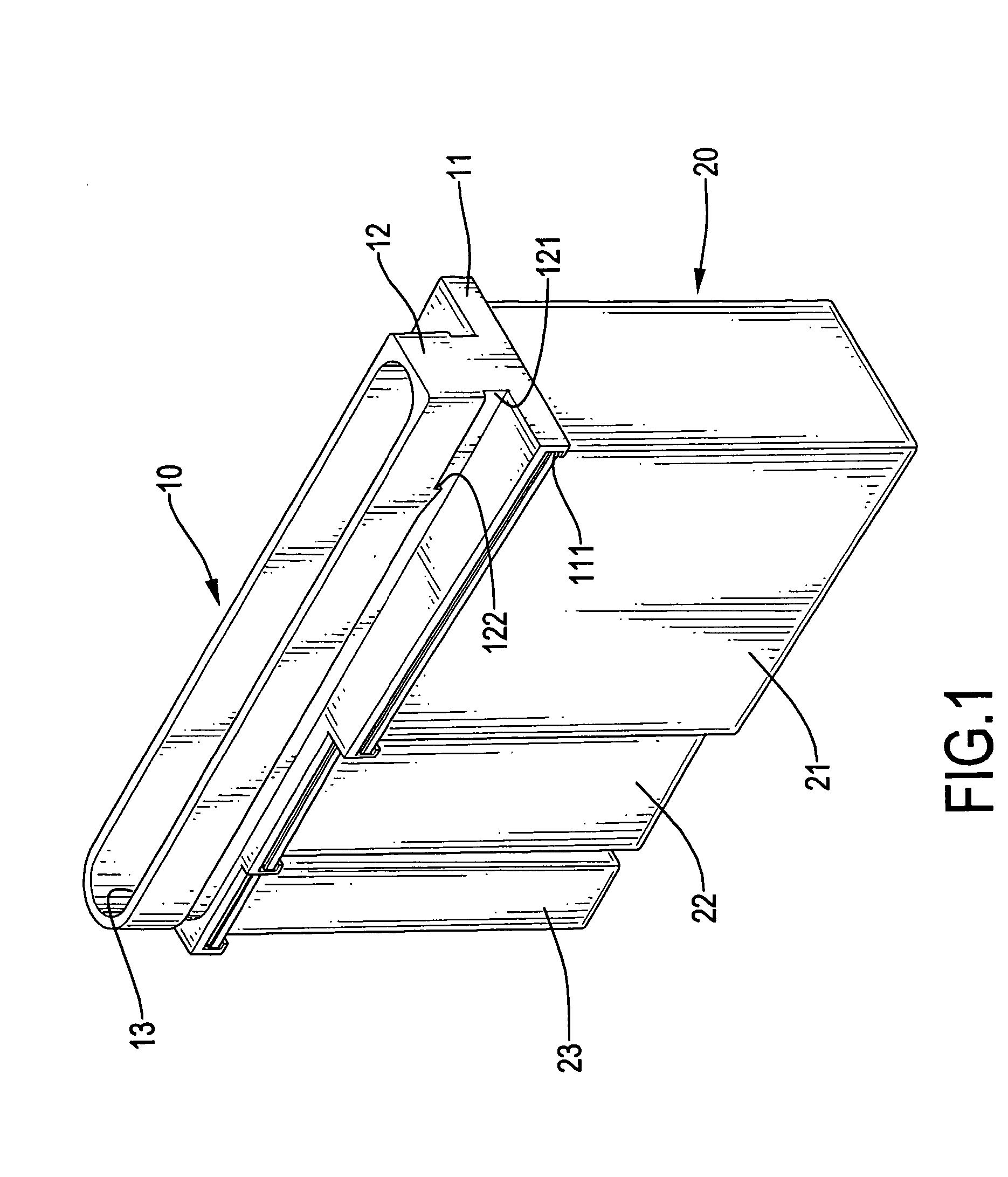
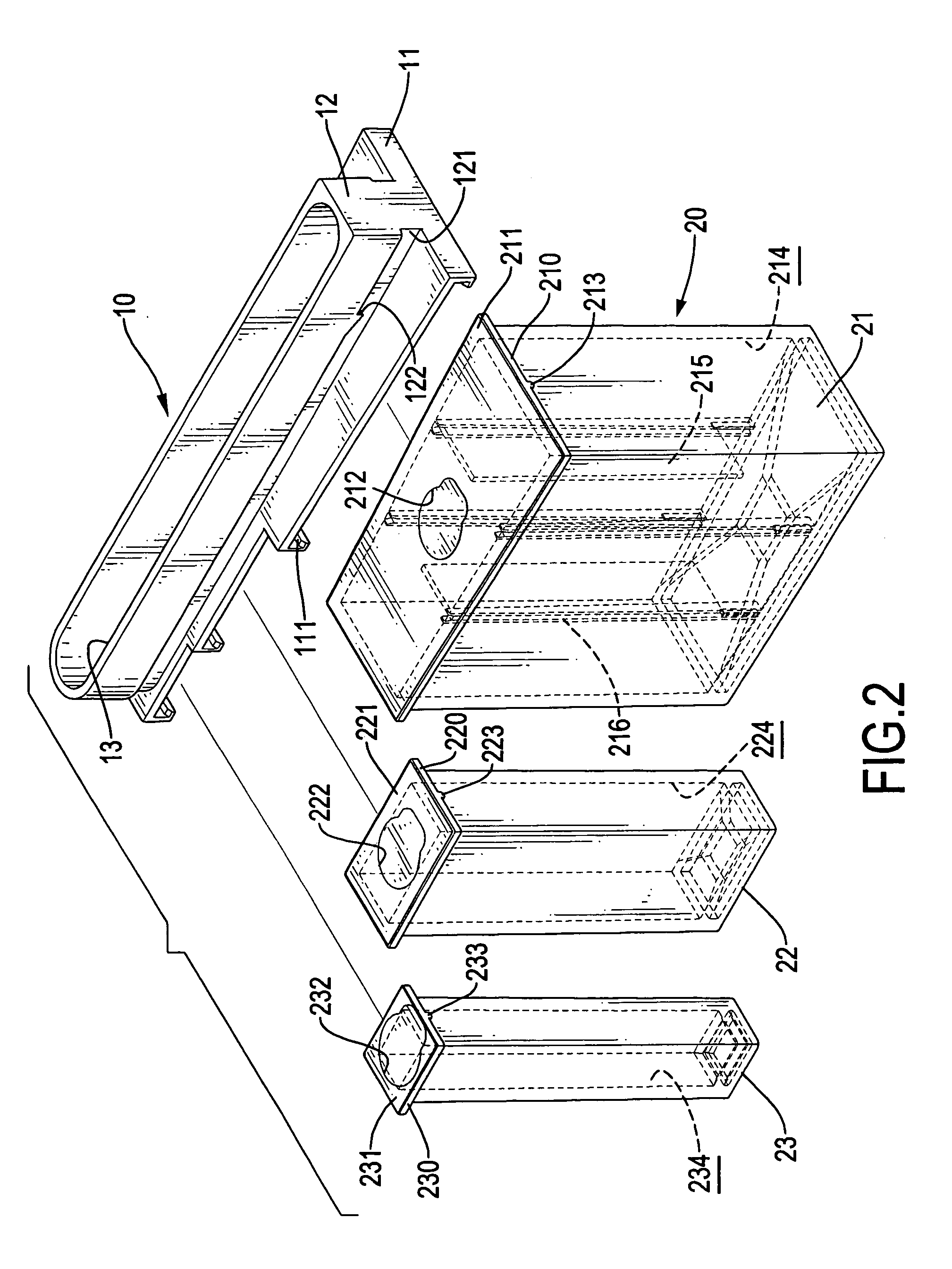
[0014] With reference to FIGS. 1 to 3, a reagent cartridge in accordance with the present invention has a cap (10) and multiple storage compartments (20).

[0015] The cap (10) has a top (11) and an insert key (12). The top (10) is formed as a trapezoid and has a top surface, a bottom surface and multiple cartridge receivers. In a preferred embodiment, three cartridge receivers are formed. The three cartridge receivers are formed on the bottom surface of the top (11) and are adjacent to each other. The sizes of the three cartridge receivers diminish in sequence. Each adjacent cartridge receiver has four side edges, an opening (113), a pair of keyways (111), an optional locking device and an optional rear side (114). The opening (113) of each cartridge receiver is defined in one of the side edges, and the rear side (114) of each cartridge receiver is formed on one of the side edges opposite to the opening (113). In a preferred embodiment, the respective openings (113) of adjacent cartr...


PUM


Abstract

A reagent cartridge has a cap and multiple reagent compartments replaceable mounted on the cap. The cap has a top and an insert key formed on the top. The top has a bottom and multiple cartridge receivers. The multiple reagent compartments are received inside the cartridge receivers. When one reagent contained inside one of the reagent compartments is empty, a user can replace the empty reagent compartment simply and conveniently.

Description

BACKGROUND OF THE INVENTION [0001] 1. Field of Invention The present invention relates to a reagent cartridge, more particularly to a replaceable reagent cartridge when a reagent becomes empty. [0002] 2. Description of the Related Art [0003] The reagent cartridge is used to contain reagents and is common in diagnostic laboratories to utilize an automatic clinical analyzer for analyzing patients' fluid samples. A conventional reagent cartridge has a top and a container. The top has three collars formed on it. Three caps are mounted respectively on the collars. The container has three storage compartments. The container is mounted on the top, and each one of the collars is corresponding to each one of the storage compartments. When one kind of a reagent contained in one of the storage compartments in the conventional reagent cartridge is exhausted, whole reagent cartridge should be discarded. Thus, the way for using the conventional is environmentally unfriendly, and surplus reagents ...

Claims


Application Information

Patent Timeline
IPC IPC(8): G01N31/22
CPCG01N35/1002B01L9/06B01L3/523
Inventor LEE, YUNG-HO
Owner IK & PP LOGISTICS EQUIP CORP
Why Eureka
Try Eureka