Muzzleloader having a lugged breech plug installable via axial rotation of 90 degrees or less

a lug and breech technology, applied in the field of muzzleloading firearms, can solve the problems of increasing the complexity and difficulty of the machining process, reducing the surface area available for lugs and retaining structures, and little or no return for the added effort, etc., to achieve easy cleaning of the barrel, facilitate the removal and the effect of speed

Inactive Publication Date: 2006-11-09
RICHARDS MARLOWE R
View PDF14 Cites 24 Cited by
  • Summary
  • Abstract
  • Description
  • Claims
  • Application Information

AI Technical Summary

Benefits of technology

[0015] The present invention fulfills the stated need for a breech plug on a muzzleloader firearm that can be removed without tools in about one second. The ease and speed of remov

Problems solved by technology

More are certainly possible, but increase the complexity and difficulty of the machining process, with little or no return for the added expenditure of effort.
In fact, because radiused cuts are produced by most machine tools, the total amount surface area available for lugs and lug retaining structures may actually decrease as t

Method used


Image

  • Muzzleloader having a lugged breech plug installable via axial rotation of 90 degrees or less
  • Muzzleloader having a lugged breech plug installable via axial rotation of 90 degrees or less
  • Muzzleloader having a lugged breech plug installable via axial rotation of 90 degrees or less

Examples


first embodiment

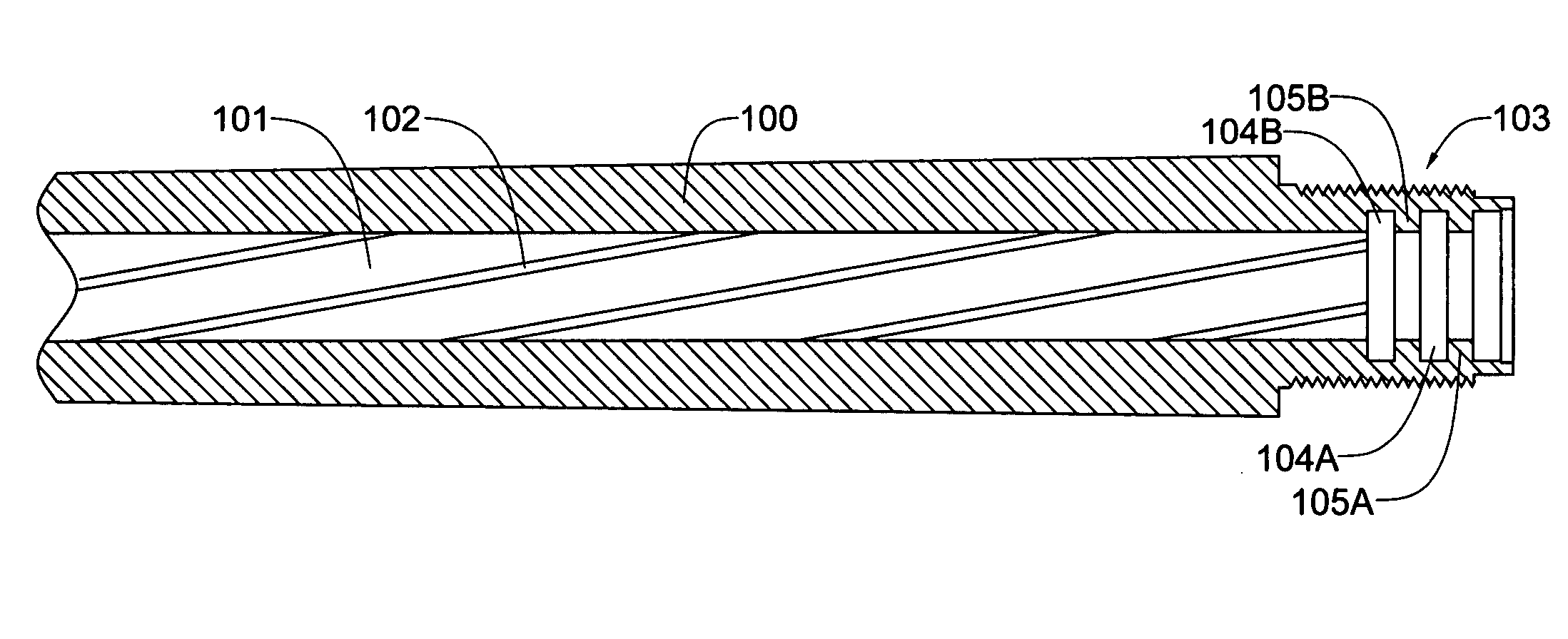
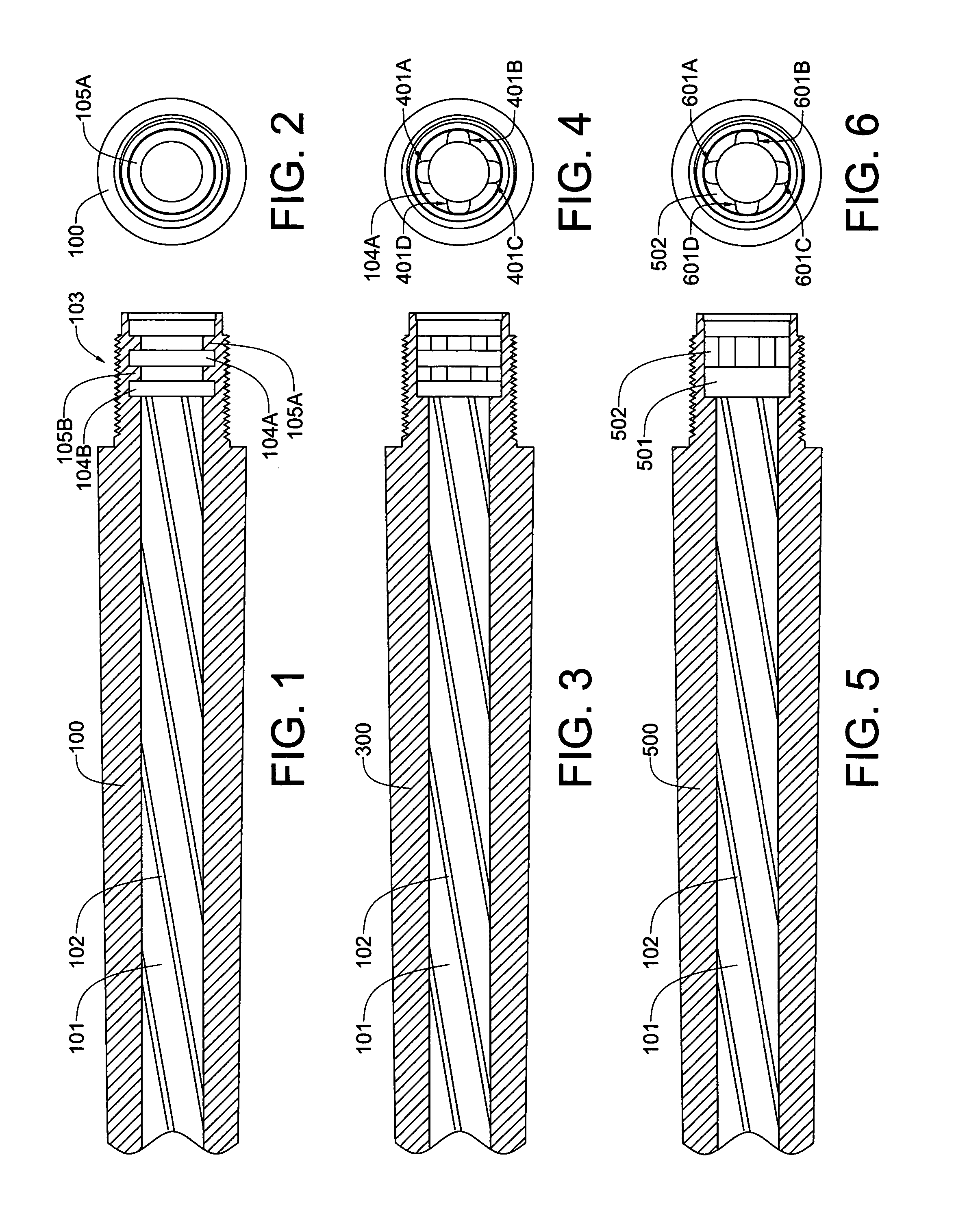
[0055] Referring now to FIGS. 3 and 4, the rifle barrel 100 of FIGS. 1 and 2 has been transformed into a completed first embodiment rifle barrel 300 by subjecting the former to an additional machining operation, whereby it is provided with four equiangularly-spaced lug entry cutouts 401A, 401B, 401C and 401D that have been cut through the first and second annular shoulders 104A and 104B.

[0056] Referring now to FIGS. 5 and 6, a second embodiment rifle barrel 500 has only a single lug retaining structure, which is comprised of a single internal groove 501 and a single internal annular shoulder 502. It will be noted that both the single internal groove 501 and the single internal annular shoulder 502 are wider than those of the first embodiment rifle barrel of FIGS. 1 to 4. However, as with the illustrated first main embodiment rifle barrel 100, four equiangularly-spaced lug entry cutouts 601A-601D have been cut through the single internal annular shoulder 502.

[0057] Referring now to ...

second embodiment

[0071] Referring now to FIG. 21, a second main embodiment non-friction-fit, four-lug breech plug 2100, installable via axial rotation of 45 degrees in the breech of the second embodiment barrel of FIGS. 5 and 6, and adapted for use with #11 primer caps, has but a single circular array of lugs 2101. It will be noted that the lugs 2102 are about twice the width of the lugs 1202 of the first main embodiment breech plug 1100 or 1400.

[0072] Referring now to FIG. 22, the second main embodiment breech plug 2100 has a front view that is identical to that of the first main embodiment breech plugs shown in FIG. 16, and the rotational locking angle for breech plugs with a four lug array is the same at 45 degrees.

third embodiment

[0073] Referring now to FIG. 23, a third embodiment rifle barrel 2300 has been created by machining three equiangularly-spaced lug entry cutouts 2301A-2301C between the annular grooves in of the rifle barrel 100 of FIG. 1.

[0074] Referring now to FIG. 24, a third main embodiment non-friction-fit breech plug 2400 has at least one circular array of three lugs 2401A-2401C. The third main embodiment breech plug is installable via axial rotation of 60 degrees in the breech of the third embodiment barrel 2300 of FIG. 23. It should be evident that a breech plug having either a single circular array of lugs, such as the second embodiment breech plug 2100 of FIG. 21, or a breech plug having a double circular array of lugs, such as the first embodiment breech plugs 1100 and 1400 of FIGS. 11 and 14, respectively, may be fabricated. Of course, the number of circular arrays of lugs on the breech plug must match the number of annular grooves and annular shoulders machined in the barrel, and the nu...


PUM


Abstract

A muzzleloader firearm has a barrel with at least one lug retaining structure that includes an internal annular groove and an internal annular shoulder that is both adjacent the annular groove and positioned between the annular groove and the breech end of the barrel. Each annular shoulder is provided with lug entry cutouts, which are radially spaced about the shoulder. The firearm also has a breech plug that is provided with multiple lugs forming at least one discontinuous external shoulder. The lugs are spaced and sized so that they align with the lug entry cutouts. Preferably, the number of external shoulders on the breech plug match the number of internal annular grooves in the barrel. The breech plug is installed in the barrel by aligning the lugs with the lug entry cutouts, and then rotating the plug so that the lugs are no longer aligned with the lug entry cutouts.

Description

BACKGROUND OF THE INVENTION [0001] 1. Field of the Invention [0002] The invention relates generally to firearms and, more particularly, to muzzle-loading firearms which require a breech plug. [0003] 2. History of the Prior Art [0004] Early in 1968, President Johnson signed into law the Omnibus Crime Control Bill, which included sundry curbs on handguns, including a ban on the interstate mail-order sale thereof. However, the President did not think that ban went far enough, and so he proposed new gun legislation targeting shotguns and rifles. After prolonged and heated debate, Congress finally enacted the strongest gun control legislation in the nation's history on October 22 of that year. As finally approved, the legislation: outlawed the mail-order sales of all rifles, shotguns, and ammunition, except between licensed dealers, manufacturers, and gun collectors; banned the sale of rifles, shotguns, and handguns to persons under 21 years of age; and banned direct sales of guns to out...

Claims


Application Information

Patent Timeline
IPC IPC(8): F41C7/00
CPCF41C9/08
Inventor RICHARDS, MARLOWE R.
Owner RICHARDS MARLOWE R
Why Eureka
Try Eureka