Article surveillance tag having a metal clip

a metal clip and surveillance tag technology, applied in the field of security tags, can solve the problems of increasing the susceptibility of defeat of the attaching assembly by vertical movement of the clamp, easy defeat of the preventing mechanism of the '419, and easy defeat of instant devices in this manner

Inactive Publication Date: 2006-11-09
SAYEGH ADEL O +1
View PDF4 Cites 2 Cited by
  • Summary
  • Abstract
  • Description
  • Claims
  • Application Information

AI Technical Summary

Benefits of technology

[0011] Therefore, it is a primary objective of the invention to provide an EAS tag that is more difficult to defeat.
[0013] It is another objective of the invention to provide an EAS tag that is durable.
[0016] In keeping with the principles of the present invention, a unique EAS tag is disclosed wherein no channel is defined therein that will guide an unauthorized probe to the attaching member. The interior of the tag further has numerous partitions and pillars that will prevent insertion of the unauthorized probe if inserted in the wrong plane. In addition, the EAS tag will deflect the unauthorized probe into false paths.
[0018] Furthermore, an apex region of the EAS tag that encloses the attaching member has a honeycombed shape such that unauthorized probes cannot be inserted into holes created above the attaching member to manipulate the same.

Problems solved by technology

Accordingly, an unscrupulous individual may easily defeat the preventing mechanism of the '419 and '390 devices by manipulating an illicitly acquired freestanding arcuate probe.
The instant device is more difficult to defeat in this manner.
Consequently, the vertical movement of the clamp increases the susceptibility of defeat of the attaching assembly because the jaws expand more easily because the angle of the clamp varies between the first end and second end as a result of the vertical movement of the non-secure end.
The prior art does not address the need for an EAS tag that is difficult to defeat.
In addition, the prior art fails to provide a clamp assembly that requires greater pull force to disengage a pin from the clamp assembly.
Furthermore, the prior art fails to provide a tag that is more difficult to defeat even when an unscrupulous individual has illicitly acquired a freestanding arcuate probe.

Method used


Image

  • Article surveillance tag having a metal clip
  • Article surveillance tag having a metal clip
  • Article surveillance tag having a metal clip

Examples


Embodiment Construction

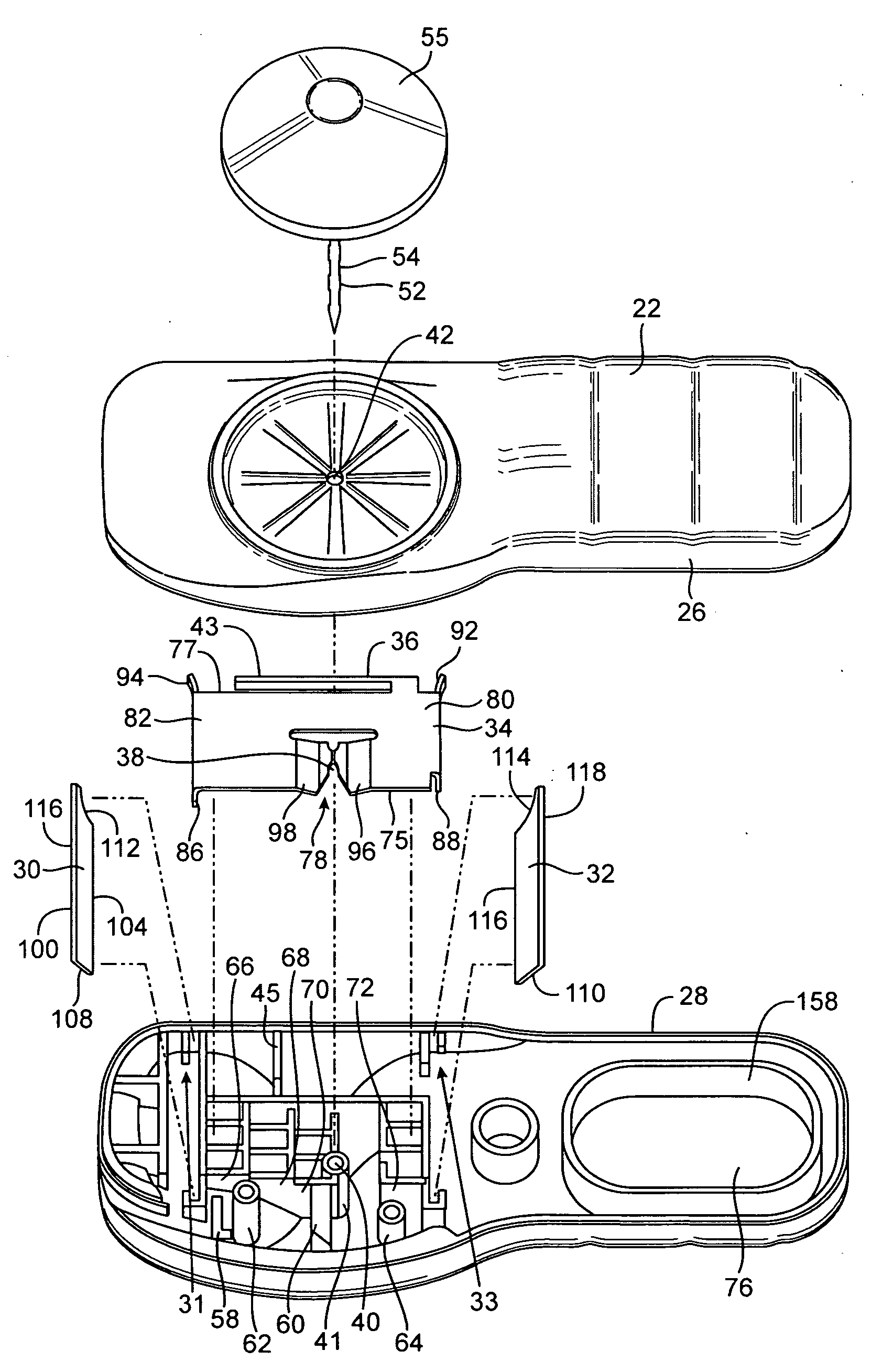
[0046] Referring now to FIGS. 1 and 2, a tag 20 is illustrated having a first half 22 and a second half 24. First and second halves 22 and 24 are preferably made of a hard or rigid material. A usable rigid or hard material might be a hard plastic such as, for purposes of illustration but not limitation, an injection molded ABS plastic. If a plastic material is used, the mating of a first side wall 26 to a second side wall 28 can accomplished via an ultrasonic weld or like joining mechanism. However, it is to be understood that other joining methods, such as adhesives, may also be used. When first half 22 and second half 24 are securely joined, first sidewall 26 and second sidewall 28 form a peripheral outer wall of tag 20. Second half 24 has an apex region 25 that extends therefrom in an opposing direction to first half 22.

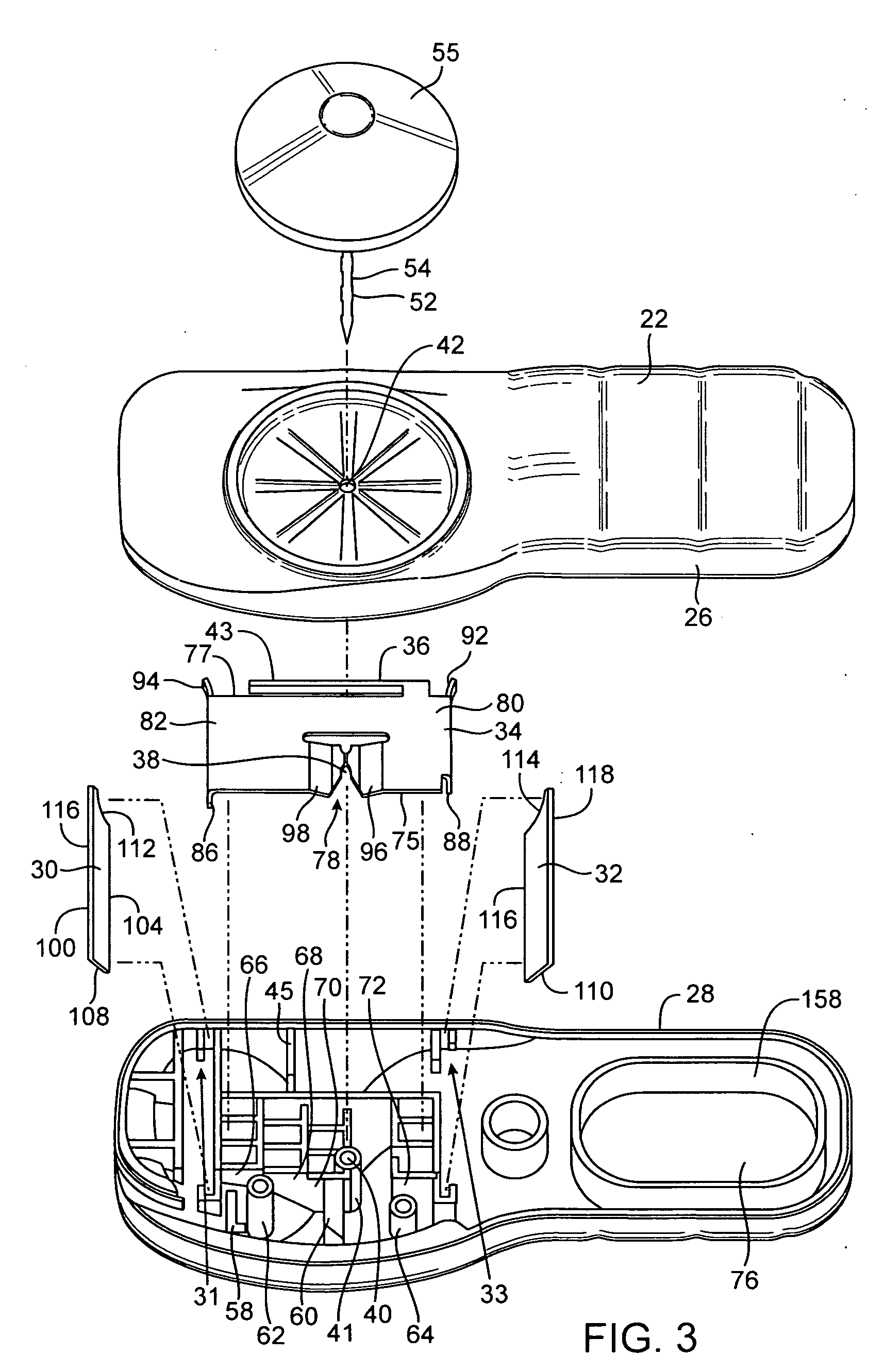
[0047] Now referring to FIG. 3, 4, 5, 11, and 11A, an exploded perspective view, top plan view, and perspective views illustrate the interior of second half 24. ...


PUM


Abstract

An electronic article surveillance (EAS) tag 20 having a metal attaching member 34 located therein and adapted to securely and releasably receive a shaft 52 of a pin therein, whereby a predetermined arcuate probe is inserted through an opening and applies a requisite force to the attaching member 34 to release the shaft 52. There are no channels leading the authorized arcuate probe to the attaching member 34. A plurality of partitions 58 and pillars 62 are interspersed within tag 20 to deflect any unauthorized probes from engaging and detaching attaching member 34.

Description

CROSS-REFERENCE TO RELATED APPLICATIONS [0001] The contents of this application are related to a provisional application having Ser. No. 60 / 371,063 filed on Apr. 8, 2002, the contents of which are incorporated herein by reference.FIELD OF THE INVENTION [0002] The invention relates to security tags in general, and in particular to a tag body containing an attaching means for use in electronic article surveillance (EAS) tags. BACKGROUND OF THE INVENTION [0003] Various types of electronic article surveillance (EAS) systems are known having the common feature of employing a marker or tag which is affixed to an article to be protected against theft, such as merchandise in a store. When a legitimate purchase of the article is made, the marker can either be removed from the article, or converted from an activated state to a deactivated state. Such systems employ a detection arrangement, commonly placed at all exits of a store, and if an activated marker passes through the detection system,...

Claims


Application Information

Patent Timeline
Patent Type & Authority Applications(United States)
IPC IPC(8): G08B13/14E05B73/00
CPCE05B73/0017E05B73/0064Y10T24/505Y10T24/50G08B13/2434Y10T70/8595Y10T70/778Y10T70/5004Y10T70/8622Y10T70/7915
Inventor SAYEGH, ADEL O.ABBOTT, RUSSELL
Owner SAYEGH ADEL O
Why Eureka
Try Eureka