Tamper resistant power receptacle

a power receptacle and tamper-resistant technology, applied in the direction of coupling device connection, two-part coupling device, electrical apparatus, etc., can solve the problem of not being able to be removed when, and achieve the effect of easy and inexpensive manufacture and hard defea

Active Publication Date: 2021-05-18
SANDEL VERNON R
View PDF49 Cites 1 Cited by
  • Summary
  • Abstract
  • Description
  • Claims
  • Application Information

AI Technical Summary

Benefits of technology

[0012]It is the object of this invention to provide the following: 1) Tamper resistant receptacles that are very hard to defeat. 2) Tamper resistant receptacles that accept a plug as easily as the former non-safety standard receptacles. 3) Tamper resistant receptacles which fit the standard electrical boxes and have shape and form factors that are essentially the same as the formerly used non-tamper resistant power receptacles. 4) Tamper resistant receptacles that eliminate possible dangers from plugs only partially inserted or pulled out, having partially exposed blades. 5) Tamper resistant receptacles that can be easily and inexpensively manufactured. 6) Tamper resistant receptacles which work with all standard plugs, whether they are of the two or three prong variety, polarized or not, or whether they have holes in the blades or not.

Problems solved by technology

The blade locks retain the plug in the socket until the switch is turned off, so that it cannot be removed when in the powered condition.

Method used


Image

  • Tamper resistant power receptacle
  • Tamper resistant power receptacle
  • Tamper resistant power receptacle

Examples


second embodiment

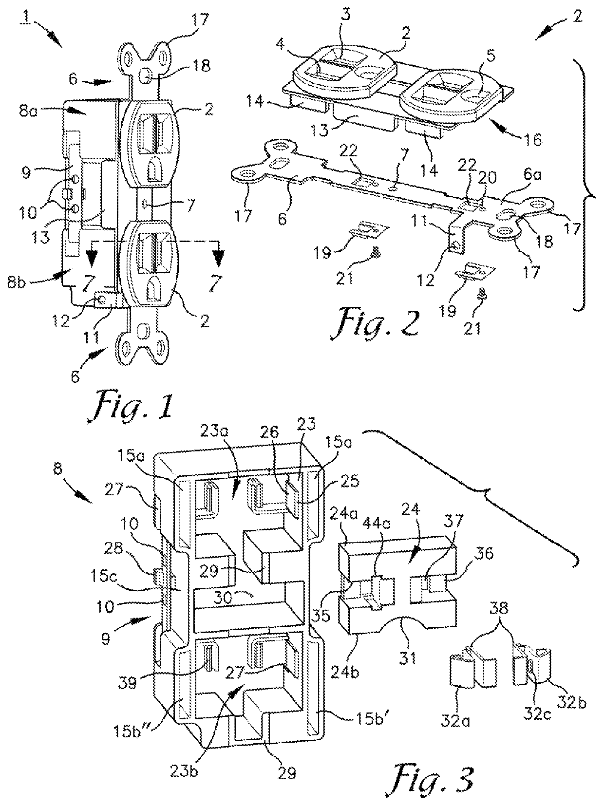
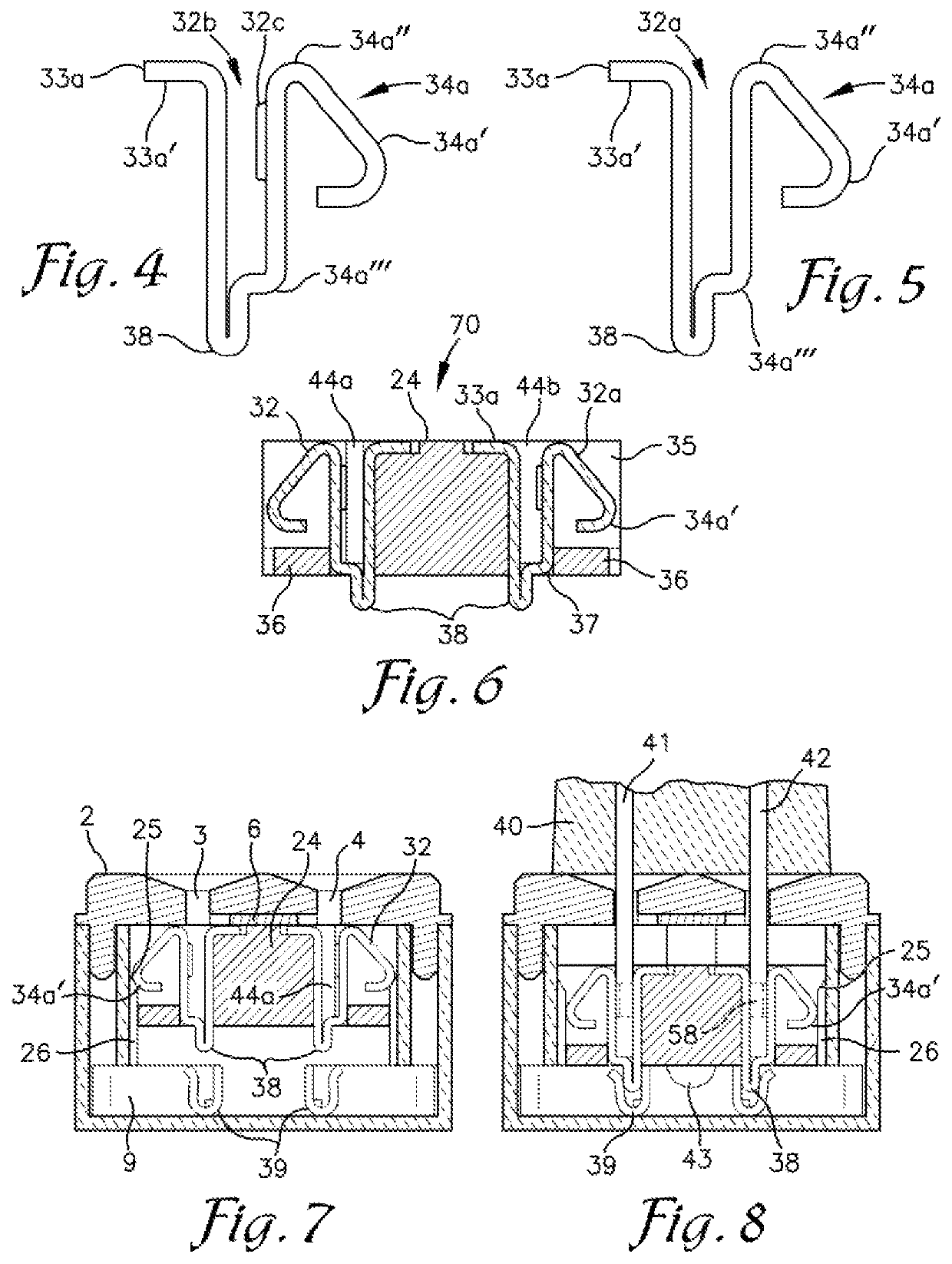
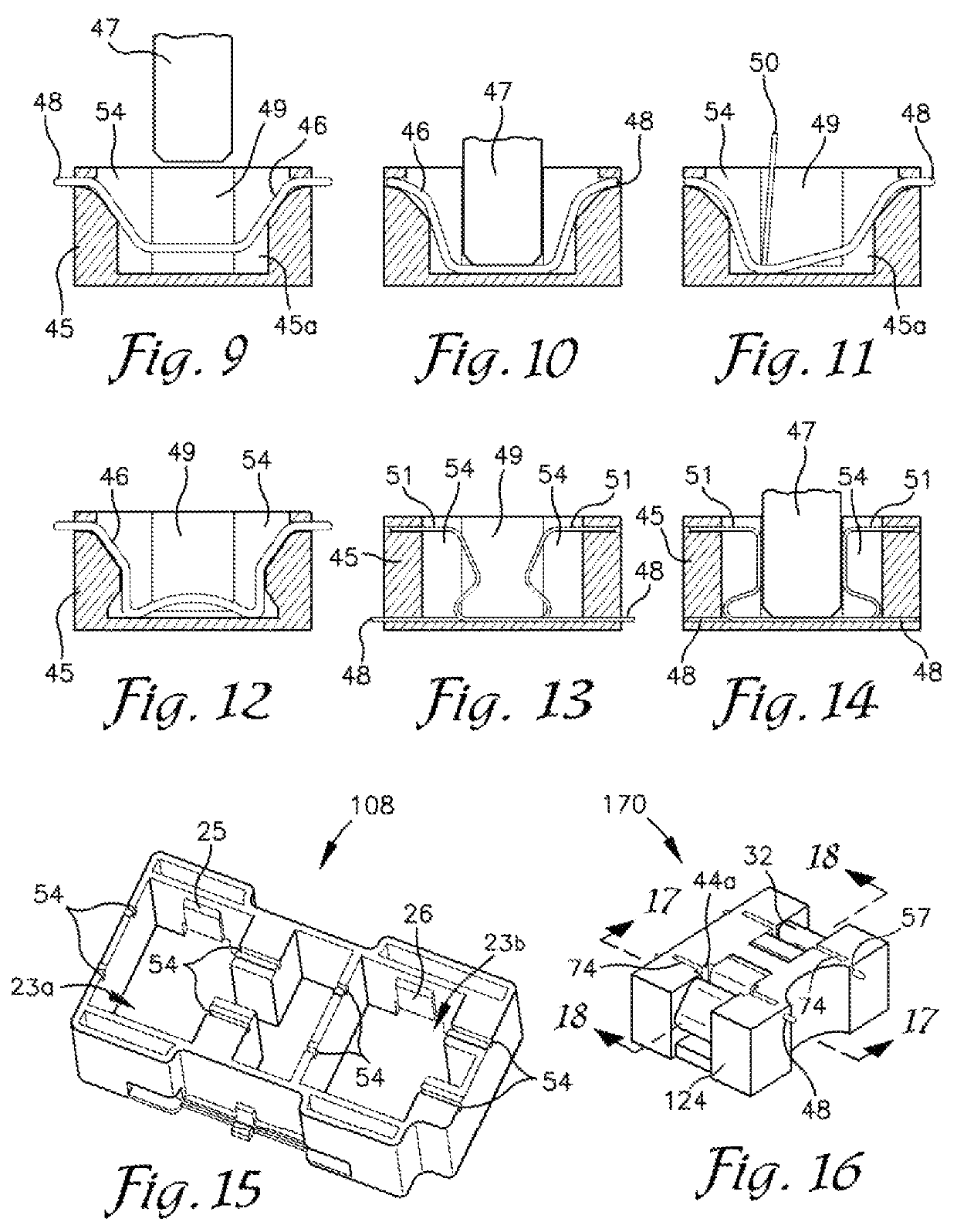
[0102]The operation of the tamper resistant receptacle is best shown in FIG. 19 which is a cross-section view looking in the direction of the arrows 7-7 in FIG. 1. When a plug is inserted into this second embodiment of the tamper resistant receptacle represented by FIG. 1, the power blades pass through the power slots 3 and 4 of the top cap 2 (FIG. 2), pass into slots 44 and 44a (FIG. 18), press the resilient members 46 into the pocket 45a (FIG. 17), retracting the resilient member ends 48 into the socket 170. Further pressure on the plug overcomes the moderate resistance provided by the compression of the blades by the blade contacts' dependent lips 34a′ (FIG. 19) interference with short ramp 25 (FIG. 15) locking the plug into the sliding socket assembly, or plug blade locking mechanism 170, sliding the assembly 170 down the ramp 25 and ramp extension 26, placing the switch tabs 38 into the switch receivers 39, thus powering the plug. It is important that the force necessary to def...

fourth embodiment

[0110]A sliding socket assembly 470 of this fourth embodiment of the receptacle represented by FIG. 1 is assembled from the socket base 424, two blade contacts 432, two blade lock springs 434, two movement lock resilient members 46, and a resistance coil spring 450. The socket base 434 is basically a rectangular block with the arcuate cutout 431 common to all the sliding socket bases as shown in FIG. 28. Other features of the socket base are shown in FIGS. 26, and 28-31. The socket base 424 has rectangular slots 425 near its longitudinal ends adapted for receipt of “L” shaped blade lock springs 434, recesses 401 whose purpose is to allow the short ends of the blade lock springs 434 to bend downward, and two slots 433 adapted to mount the blade contacts 432 which protrude through the lower ends of these slots to present switch tabs 438. The blade slots 44a and 44b for the neutral and hot blades of a plug (not shown) are formed between the blade contacts 432 and the outer wall of this...


PUM


Abstract

The present invention provides safety power outlets having the form and size to fit standard electrical boxes. The present invention includes one or more switched sockets which are generally switched on by movement from a first position to a second position. The described movement is prevented by one or more locks configured to be unlocked by complete insertion of a plug's power blades into the socket. In addition, blade locks are provided to prevent removal of the plug once the movement from the first position to the second position has begun. The movements described herein are both linear and rotary. Embodiments adapted for use with an extension cord socket are also presented.

Description

CROSS-REFERENCE TO RELATED APPLICATIONS[0001]The application claims the benefit of the prior filed U.S. provisional application No. 62 / 128,868 filed on Mar. 5, 2015 which is incorporated herein by reference.FIELD OF THE INVENTION[0002]The present invention is broadly directed to power outlets and, more particularly, to an improved safety power outlet which has a child-proof, tamper resistant features.BACKGROUND OF THE INVENTION[0003]An inexpensive, convenient and easy to manufacture safety electrical power receptacle has long been sought to protect children. These have taken the form of devices which block the access slots for the plug blades or switched outlets wherein the contacts in the electrically active slots are not connected to power until a plug is inserted. Since 2008 the National Electrical Code has required tamper resistant (child resistant) power receptacles in all new residential construction and renovation. One type of commonly available commercial products that meet ...

Claims


Application Information

Patent Timeline
Patent Type & Authority Patents(United States)
IPC IPC(8): H01R13/71H01R13/44H01R24/78
CPCH01R13/71H01R13/44H01R24/78
Inventor SANDEL, VERNON R.
Owner SANDEL VERNON R
Why Eureka
Try Eureka