Track rod

Inactive Publication Date: 2002-12-17
WINKLER MORRIS B
View PDF11 Cites 0 Cited by
  • Summary
  • Abstract
  • Description
  • Claims
  • Application Information

AI Technical Summary

Benefits of technology

Applicant's track rod is a sliding door and window stop that can be adjusted to fit any standard size sliding door or window. The track rod can be adjusted for an opening to allow for ventilation while still keeping the sliding door or window from being opened any further. The track rod is fully adjustable and yet locks to any length, in a manner which makes it very secure and extremely difficult to break or defeat. The track rod is preferably made of high-

Problems solved by technology

Theft from homes is a major problem in society today.
One particularly vulnerable location in a home is any sliding glass door or window.
They are easily broken and the door or window slid open.
In doing so, no security exists, as there is no method to secure the open door or window, which can easily be slid further open and the home entered by unwanted persons.
Existing technology for door and window stops exis

Method used


Image

  • Track rod
  • Track rod
  • Track rod

Examples


Embodiment Construction

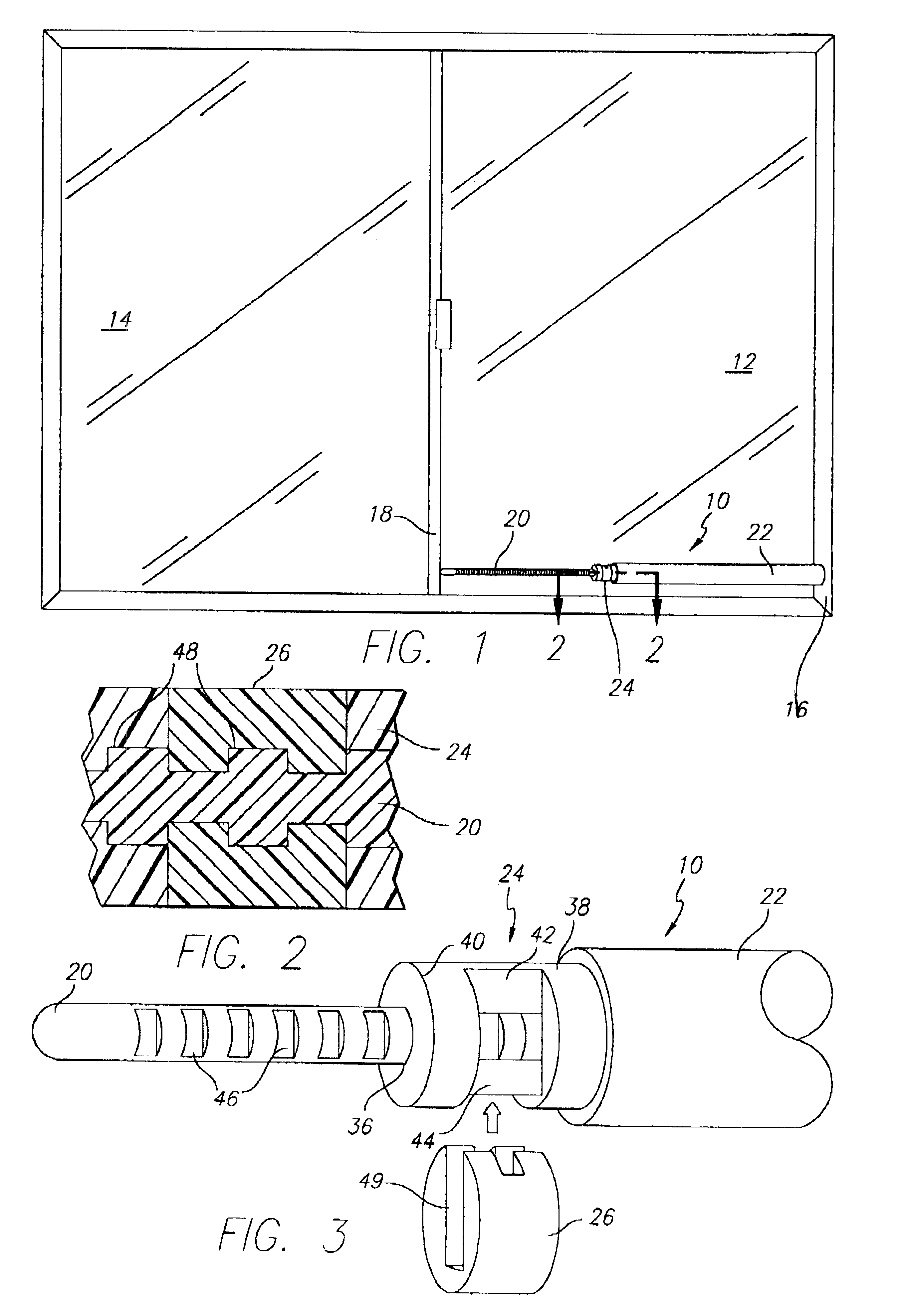
Referring now to FIGS. 1-4, there is shown the track rod 10 of this invention located in a sliding glass door which comprises the fixed pane 12 and the sliding door 14. Track rod 10 is placed between the frame 16 of pane 12 and the front edge 18 of door 14.

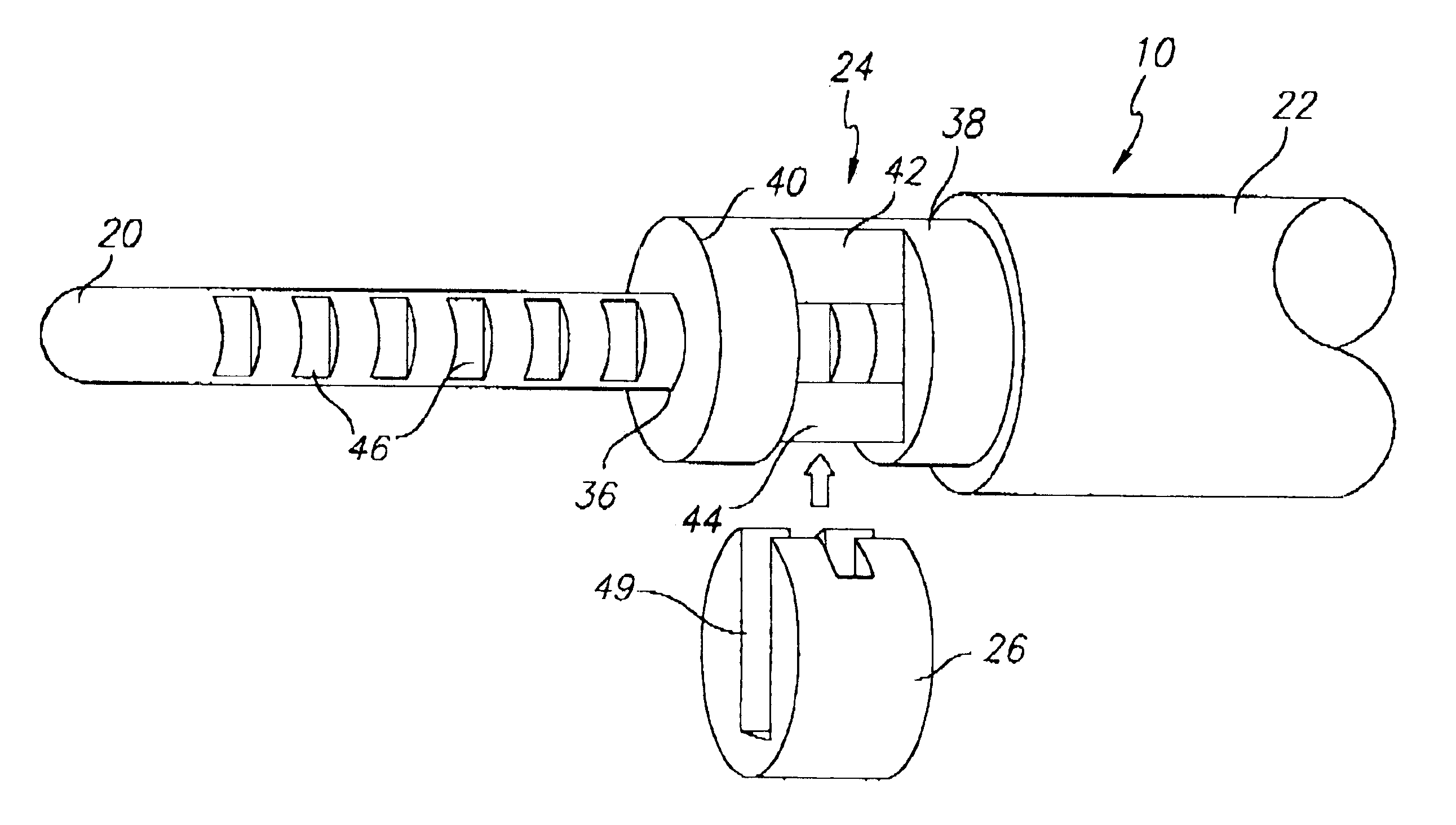
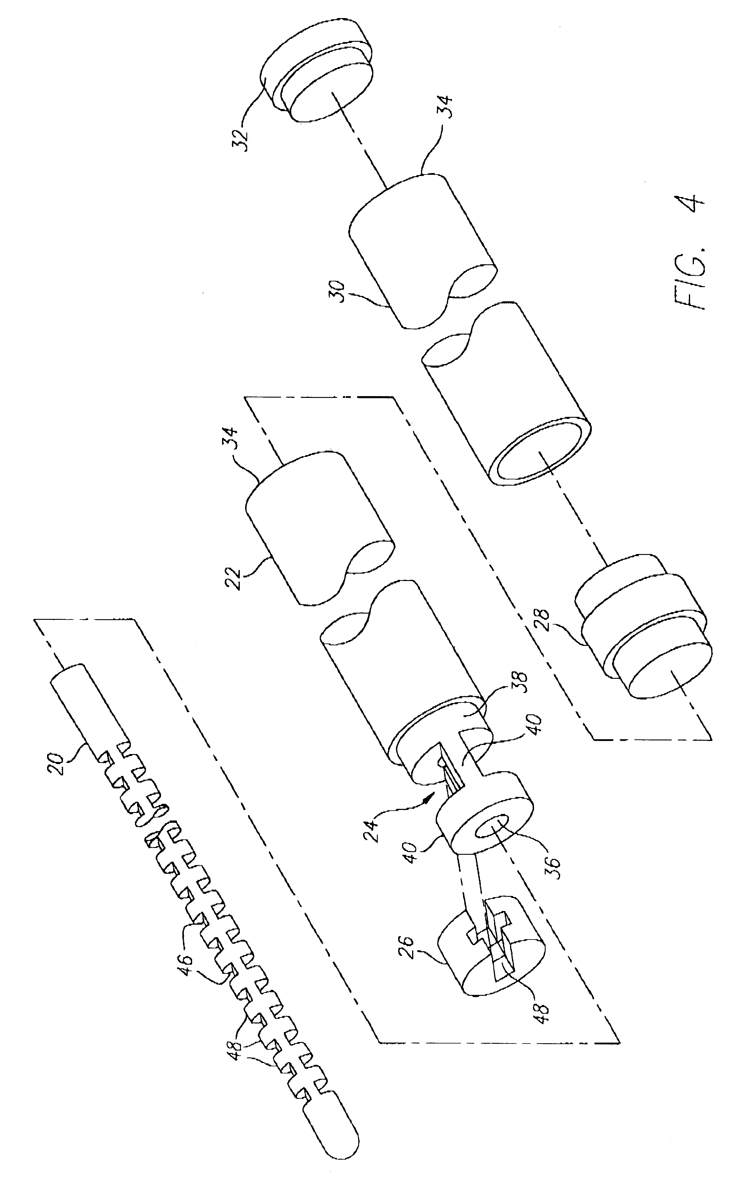
Track rod 10 comprises dowel 20, hollow rod or tube 22, locking pin 24 and locking clip 26. Coupler 28 is optionally utilized to attach hollow rod section 30 to hollow rod section 22, combining two sections of hollow rod together to lengthen the track rod if needed. Removable end cap 32 is placed on the end 34 of rod 30, or if only one rod is needed, on end 34 of rod 22.

Dowel 20 is just slightly smaller in diameter than circular bore or opening 36 through the center of locking pin 24. Dowel 20 telescopes, that is, passes completely through locking pin 24 and into hollow rod 22. This is accomplished by locking pin 24 comprising two circular or annular portions 38 and 40 connected by two rectangular cross-strips 42 and 44, leaving s...


PUM


Abstract

An adjustable sliding door and window track rod comprising an elongated hollow rod into which a dowel fits telescopically, the dowel having a plurality of alternating slots and raised teeth, a locking pin, which frictionally fits into the hollow tube, and has a central bore through which passes the dowel. A locking clip fits over the locking pin and engages the teeth of the dowel, locking the dowel from moving into or out of the hollow rod, fixing the length of the track rod.

Description

The invention relates to the field of door and window stops.Theft from homes is a major problem in society today. One particularly vulnerable location in a home is any sliding glass door or window. They are easily broken and the door or window slid open. Also, homeowners often desire to leave the door or window open for ventilation purposes. In doing so, no security exists, as there is no method to secure the open door or window, which can easily be slid further open and the home entered by unwanted persons.Existing technology for door and window stops exist but suffer from the problem of being unstable and not strong enough to be safe. Examples of such stops are described in U.S. Pat. 4,792,168 and 4,971,374. These stops, while usable to adjustably hold a door closed, or to allow it to be open somewhat, are adjustable by placing pins through one of a series of holes in the device. These pins can be easily lost or broken, so that the devices shown are not secure. In addition lining ...

Claims


Application Information

Patent Timeline
IPC IPC(8): E05B65/08
CPCE05B65/0888Y10S292/46Y10T292/23
Inventor WINKLER, MORRIS B.
Owner WINKLER MORRIS B
Why Eureka
Try Eureka