Multifunctional mechanical working table capable of working in multi-angle mode

A multi-angle, multi-functional technology, applied in the direction of manufacturing tools, other manufacturing equipment/tools, etc., can solve the problems of inconvenient processing, poor operation effect, single operation direction, etc., to achieve improved operation efficiency, convenient operation, and comprehensive functions Effect

Active Publication Date: 2018-05-25
肇庆市高要区博斯五金制品有限公司
View PDF5 Cites 12 Cited by
  • Summary
  • Abstract
  • Description
  • Claims
  • Application Information

AI Technical Summary

Problems solved by technology

[0003] The mechanical workbench is one of the commonly used equipment in hardware production. The mechanical workbench for processing work can only be used for grinding or cutting hardware parts. The functionality of the mechanical workbench is poor, and the use is relatively limited. It cannot be better for the work. It provides greater convenience, and the current work does not have a good angle adjustment function, and the orientation of the work is relatively single. Fo

Method used


Image

  • Multifunctional mechanical working table capable of working in multi-angle mode
  • Multifunctional mechanical working table capable of working in multi-angle mode
  • Multifunctional mechanical working table capable of working in multi-angle mode

Examples


Example Embodiment

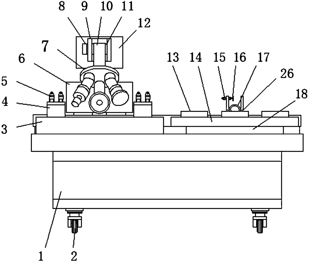
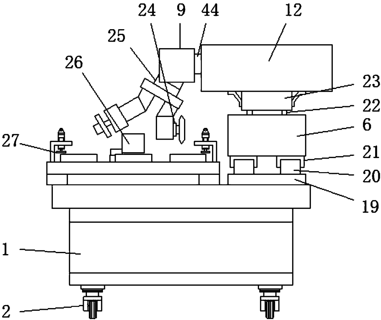
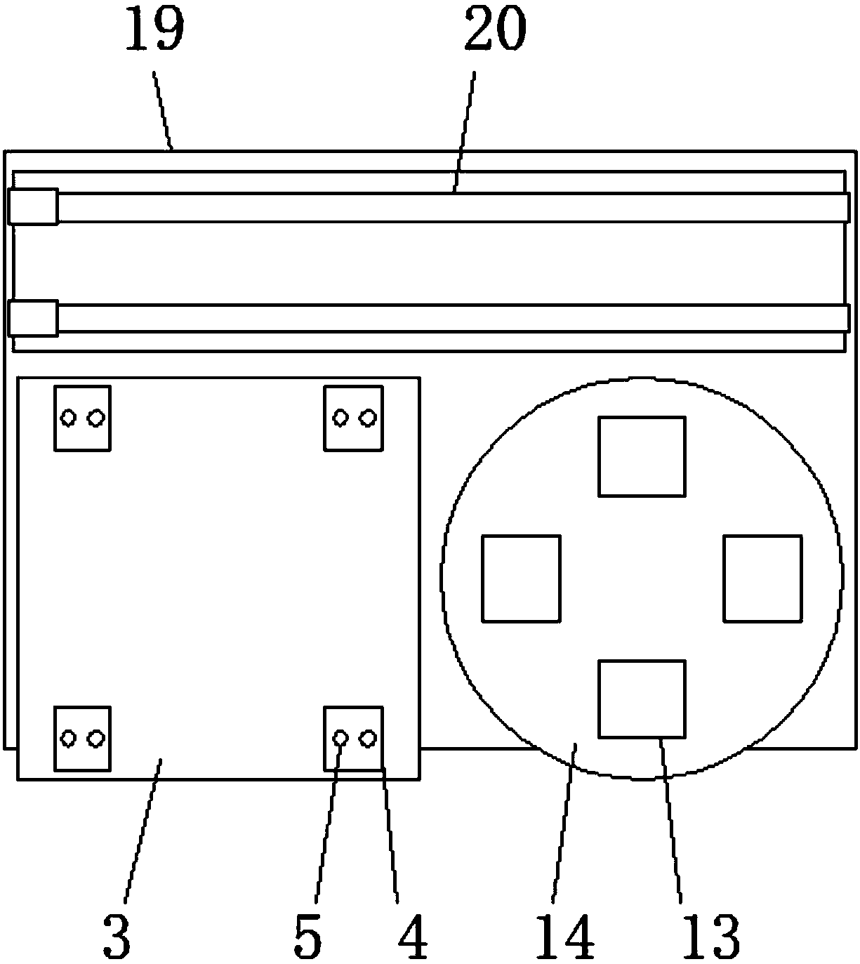
[0027] Example 1, as figure 1 , Figure 5 First, the object to be cut is placed on the cutting table 3, and the object is fixed on the cutting table 3 by the L-shaped splint 4 and the first pneumatic cylinder 5. First, the turntable 7 is driven by the third rotating motor 25 to adjust the cutting blade 34 to the working position. The working part of the first electromagnetic sliding rail 20 and the first electromagnetic slider 21 can be moved to a designated position above the cutting table 3, and the sliding column 44 can be slid by the second electromagnetic sliding rail 39 and the second electromagnetic slider 40, and further The position of the cutting blade 34 is adjusted, and then the lifting air cylinder 42 drives the cutting blade 34 to move up and down, so that the cutting blade 34 is in contact with the part to be cut, and the cutting blade 34 is driven to run to cut the part, while passing through the first electromagnetic slide rail 20 And the first electromagneti...

Example Embodiment

[0028] Example 2, as figure 1 , Figure 4 When grinding a regular object, the grinding piece can be placed inside the placement slot 13, and the object can be fixed inside the placement slot 13 by the fixing spring 45 and the splint 46, and then the first electromagnetic slide rail 20 and the first electromagnetic slider. 21 Adjust the position of the second mounting seat 12, and adjust the sliding column 44 with the second electromagnetic slide rail 39 and the second electromagnetic slider 40, so that the working part is located above one of the placement slots 13, and is driven by the third rotating motor 25. The turntable 7 rotates, adjusts the grinding head 31 to the working position, controls the lifting and lowering of the working position through the lifting and lowering air cylinder 42, adjusts the grinding head 31 to a specified height, and drives the first grinding motor 30 through the first grinding motor 30 to grind the object. At the same time, the other stations...

Example Embodiment

[0029] Example 3, as figure 1 , Figure 4 When the irregular object needs to be ground, place the irregular object inside the U-shaped splint 26, fix the object through the second pneumatic cylinder 15 and the splint 16, select the grinding method according to the specific situation, and grind the grinding head 31 and the grinding head 31 to the ground. The disc 35 is adjusted in the working position, and the grinding head 31 or the grinding disc 35 is driven to grind the designated position by the first grinding motor 30 and the second grinding motor 36 respectively. The rotating motor 8 drives the rotating shaft 11 to rotate, thereby adjusting the inclination angle of the working part, and at the same time, the second rotating motor 17 drives the fixed part to rotate, thereby adjusting the inclination angle of the object, and it is convenient to match the grinding part to specify the angle for grinding. The fourth rotating motor 48 drives the fixed part to rotate, so that d...


PUM

PropertyMeasurementUnit
Rotation angleaaaaaaaaaa

Abstract

The invention discloses a multifunctional mechanical working table capable of working in multi-angle mode. The working table comprises a machine tool, a mounting plate is arranged on one side of the machine tool, and first electromagnetic sliding rails are arranged on the two sides above the mounting plate; the top of the first electromagnetic sliding rail is provided with two sets of first electromagnetic sliding blocks, and a first installation base is arranged above the first electromagnetic sliding block; an installation groove is formed in the top of the first installation base, and foursets of lifting pneumatic cylinders are arranged in the installation grooves, the top of the lifting pneumatic cylinder is provided with a piston rod, and the top of the piston rod is provided with afixing block; and a second installation base is arranged at the top of the fixed block, and an installation hole is formed in the inner side of the second installation base. The workbench is providedwith a cutting table and a grinding table, a cutting structure and a grinding structure on the mechanical table cooperate, so that the function of the working table is more comprehensive, the polishing operation of the hardware can be realized, the cutting operation of the hardware can be realized, and the functionality is stronger.

Description

technical field [0001] The invention relates to the technical field of hardware production equipment, in particular to a multifunctional mechanical workbench capable of multi-angle processing. Background technique [0002] Traditional hardware products, also known as "small hardware", refer to five metals: gold, silver, copper, iron and tin. After manual processing, it can be made into art or metal parts such as knives and swords. The hardware in modern society is more extensive, such as hardware tools, hardware parts, daily hardware, construction hardware and security products. With the current market and social With the development of the industry, the use of hardware accessories is becoming more and more extensive, the production demand for hardware accessories is also increasing, and various hardware production equipment is becoming more and more perfect. [0003] The mechanical workbench is one of the commonly used equipment in hardware production. Generally, the mecha...

Claims


Application Information

Patent Timeline
IPC IPC(8): B23P23/04
CPCB23P23/04
Inventor 赵战锋
Owner 肇庆市高要区博斯五金制品有限公司
Why Eureka
Try Eureka