Adjustable plumbing fittings

a technology of plumbing fittings and adjustable fittings, which is applied in the direction of adjustable joints, water installations, construction, etc., can solve the problems of increasing the difficulty and time required to complete an installation, clogging of pipes, etc., and achieves the effect of accurate measurement and cutting pipes, convenient connection of drains and overflows, and easy adjustment of the height of flanges

Inactive Publication Date: 2007-03-15
SHAFIK AASEF
View PDF19 Cites 13 Cited by
  • Summary
  • Abstract
  • Description
  • Claims
  • Application Information

AI Technical Summary

Benefits of technology

[0016] The present invention is a telescopic plumbing fitting that is substantially devoid of sharp internal shoulders, is simple in construction, involves a minimum number of parts, is easy to use, and provides ample adjustment to reduce the need to make accurate measurements and cuts during a typical installation.
[0027] Use of the fitting of the invention makes it unnecessary to accurately measure and cut pipes to splice them together and / or connect them with other plumbing components, and enables a standard size fitting to be used to connect components having different spacing between the parts to be connected. For example, the T-fitting of the invention, incorporating two orthogonally disposed slip joints, greatly facilitates connection of the drain and overflow of a bathtub, and permits a single fitting to be used with tubs having different spacing between the overflow and drain.
[0028] The water closet flange of the invention, incorporating a slip joint, makes it easy to adjust the height of the flange as necessary to accommodate the level of a floor in which the flange is being installed, and also permits the flange to be rotated to different angular positions to facilitate receipt of fasteners in securing a water closet to the flange.

Problems solved by technology

Moreover, each of them has interior surfaces at right angles to the direction of flow, forming obstructions that can eventually trap sediment or other debris and lead to clogging of the pipe.
The devices disclosed in the '320, '817 and '910 patents all have limited adjustment and require fairly close measurement and cutting of the drain pipe in order to achieve proper positioning of the flange.
Moreover, the '320 and '817 devices require the use of separate fasteners and assembly of multiple parts, increasing the difficulty and time required to complete an installation.

Method used


Image

  • Adjustable plumbing fittings
  • Adjustable plumbing fittings
  • Adjustable plumbing fittings

Examples


Embodiment Construction

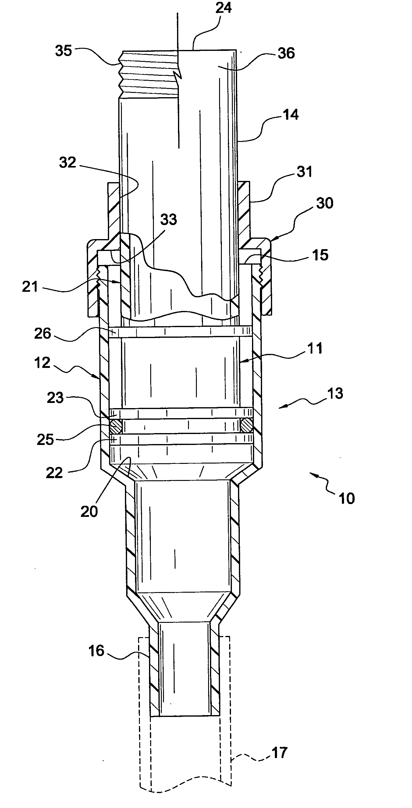
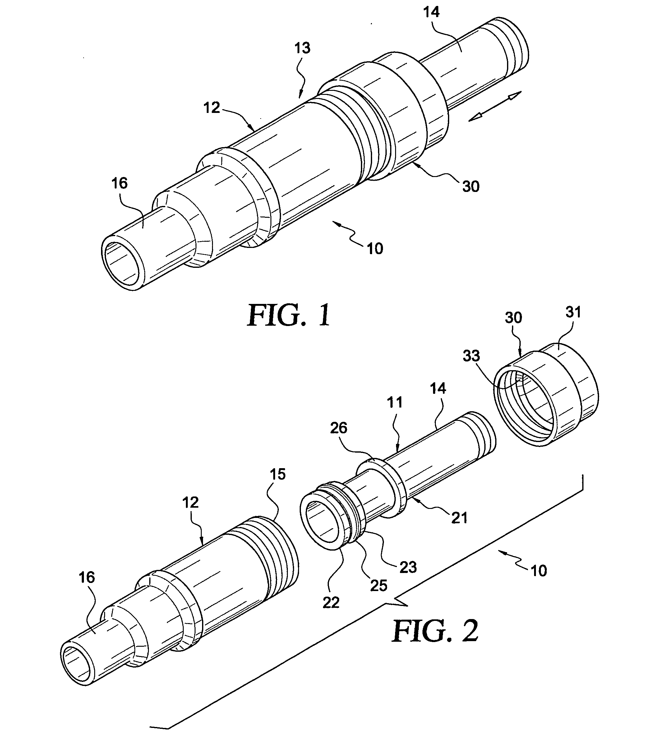
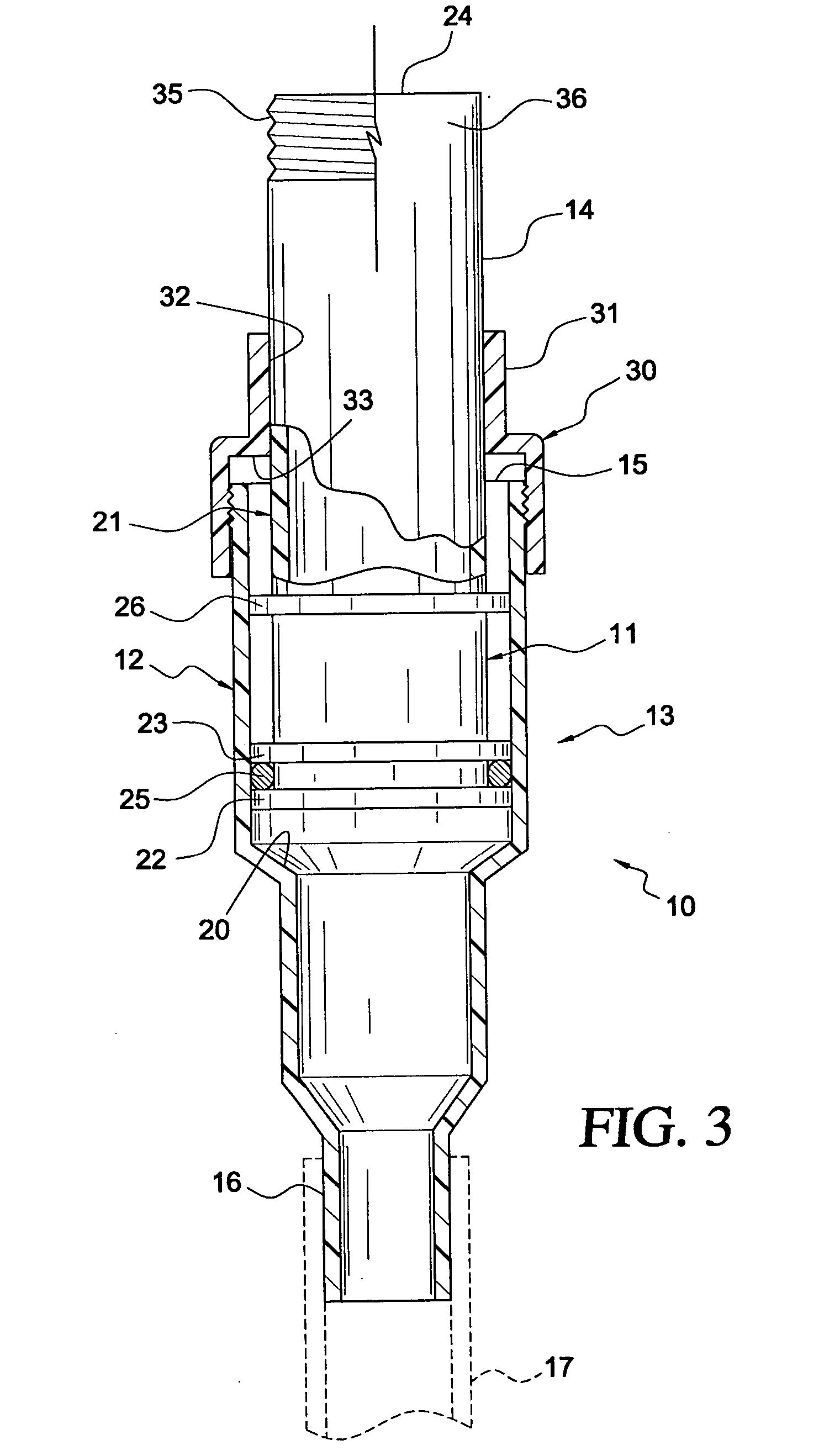
[0044] An inline fitting incorporating the slip joint of the invention is indicated generally at 10 in FIGS. 1-3. The fitting comprises a piston 11 that is both reciprocable and rotatable within a cylindrical housing 12, forming a slip joint 13. A cylindrical extension 14 of the piston projects from one end 15 of the housing for attachment to a length of pipe (not shown), or to a drain fitting (not shown), or to another device or appliance (not shown). In the embodiment shown in FIGS. 1-3, the other end 16 of the housing is a smooth-surfaced cylindrical part adapted to be connected to a pipe or other device (indicated by broken lines at 17), typically by use of an adhesive. It should be understood, however, that this could be a threaded or other connection, as desired.

[0045] The cylindrical housing 12 is open at both ends, and in the embodiment shown in FIGS. 1-3, the end 15 has a larger diameter than the end 16, defining an interior annular tapered shoulder 20 between the ends.

[0...


PUM


Abstract

An adjustable plumbing fitting has a piston rotatably and telescopically engaged in a housing, with one end of the housing adapted to be connected to a first plumbing part, and a cylindrical extension on the piston projecting from an opposite end of the housing and adapted to be connected to a second plumbing part. In one embodiment, two housings and associated pistons are integrally joined together to form a T-fitting for connecting the overflow and drain of a bathtub. In another embodiment, the housing is integrally formed with a J-shaped drain trap, and in another embodiment the housing and / or piston is integrally formed with a water closet flange.

Description

BACKGROUND OF THE INVENTION [0001] 1. Field of the Invention [0002] This invention relates to plumbing fittings, particularly to adjustable fittings that are easy to use and install. More specifically, the invention relates to adjustable closet flanges and repair couplings or tail pieces. [0003] 2. Prior Art [0004] Plumbing fittings are provided in a variety of shapes, sizes and designs to facilitate connection of pipes to each other and to appliances and fixtures such as lavatories, sinks, bathtubs, showers, water closets, and the like, and for other purposes known to those skilled in the art. For example, these fittings may be designed to couple or adapt a pipe of a first diameter to a pipe of a different diameter, or to connect the overflow and / or drain from a bathtub or sink to a drain pipe, or to connect a water closet to a sewage drain pipe, or to repair previously installed pipes or fittings, and the like. [0005] The fittings generally are provided with either a threaded conn...

Claims


Application Information

Patent Timeline
Patent Type & Authority Applications(United States)
IPC IPC(8): F16L39/04
CPCE03C1/122E03C1/20F16L27/12E03C1/284E03C1/232F16L27/1274
Inventor SHAFIK, AASEF
Owner SHAFIK AASEF
Why Eureka
Try Eureka