Anastomotic device

an anastomosis and device technology, applied in the field of anastomosis devices, can solve the problems of complex surgical procedures, time-consuming, and difficult process, and achieve the effect of facilitating reloading

Inactive Publication Date: 2006-11-23
PARK MEDICAL LLC
View PDF17 Cites 27 Cited by
  • Summary
  • Abstract
  • Description
  • Claims
  • Application Information

AI Technical Summary

Benefits of technology

[0007] The anastomotic delivery device is designed with a protective sleeve to encapsulate the woven tube and a removable nose assembly to permit the woven tube to be inserted into the protective sleeve via a loading apparatus. The woven tube is pulled longitudinally causing the tube to become longer and very small in diameter and is installed into a loading apparatus. The loading apparatus consists of a sheath and attached alignment cylinder and a plunger. The loading apparatus is designed to fit over the end of the protective sleeve of the delivery device to permit ease of reloading for multiple deployments. To load the woven tube into the delivery device, the nose assembly is removed from the delivery device and the loading apparatus is fit over the protective sleeve. The plunger of the loading apparatus moves the woven tube into the protective sleeve of the delivery device. After the woven tube is installed in the delivery device, the nose assembly is placed over the protective sleeve to encapsulate the woven tube between the nose assembly and a ram.

Problems solved by technology

This process can be technically demanding and time consuming.
This complex surgical procedure is even more challenging during minimally invasive surgery (MIS) where the surgeon is required to use instruments that are poorly designed for this task.

Method used


Image

  • Anastomotic device
  • Anastomotic device
  • Anastomotic device

Examples


Embodiment Construction

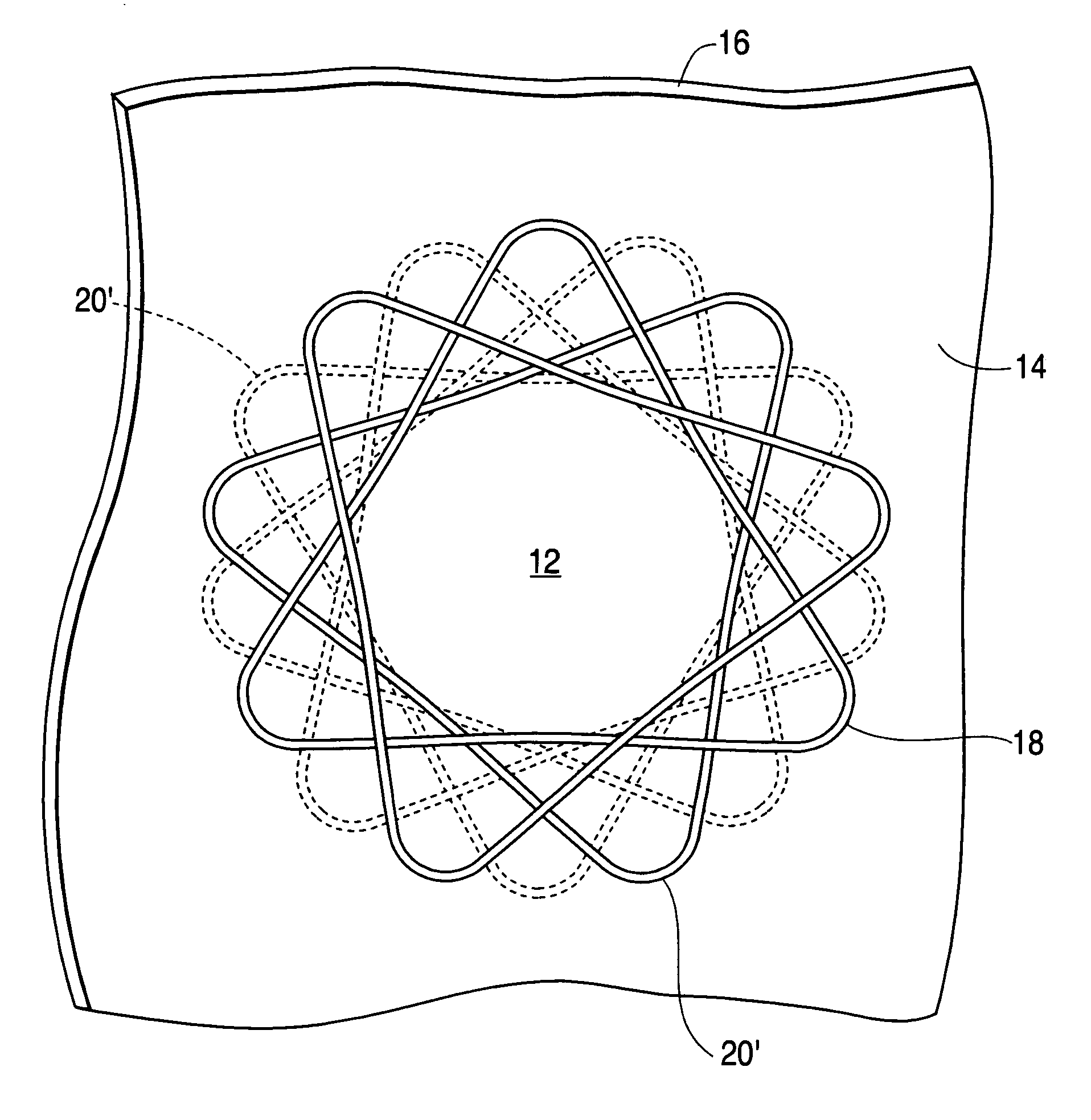
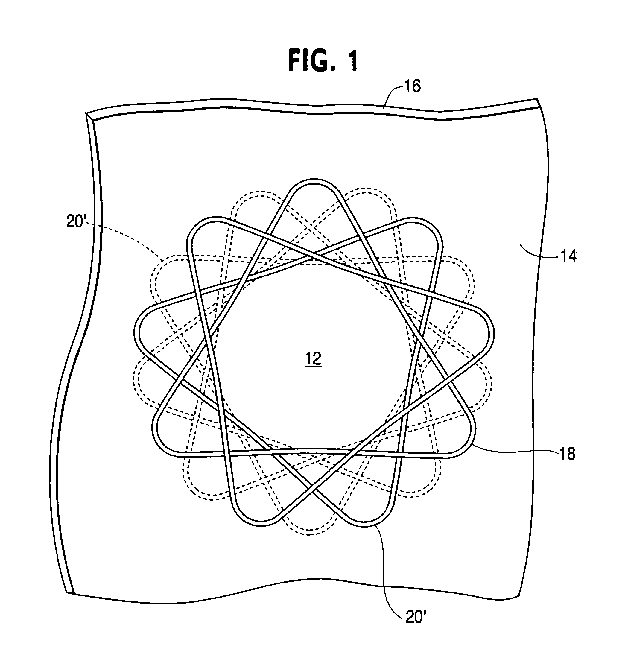
[0028] The tube 10 has an overlapping woven design. The woven tube is designed to produce a round opening 12 between two layers of tissue 14, 16 and to hold the layers of tissue together for a watertight seal. The deployed anastomic device is essentially a woven tube 10 of wire 18 that is axially compressed as shown in FIG. 1.

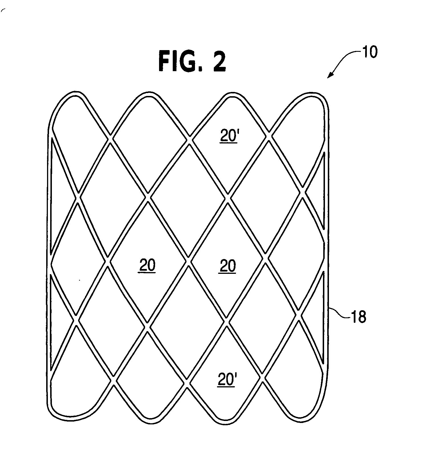
[0029] The woven tube 10 is defined by the wire diameter, number of circumferential and longitudinal openings or diamonds 20, the tube length and the center diameter. The openings or diamonds 20′ at the longitudinal ends of the elongated woven tube are referred to as petals when the device is in the deployed shape (see FIG. 1).

[0030] In use, the woven tube 10 is forced into an elongated form (with much smaller diameter than that shown in FIG. 2), placed through openings between the wall tissues of two lumens and allowed or forced to return to the flattened shape of FIG. 1. In the process, the tissues of both lumen walls are compressed between the petals of th...


PUM


Abstract

The present invention is directed to gastrointestinal or enteric (including biliary) anastomosis and the like. The anastomotic device of the invention is a three dimensional woven tube of wire. The outer loops or ends of the tube fold or loop back on deployment in a manner which holds the luminal interface of the anastomotic site into apposition at the deployment site. The woven tube is deployed using a protective sleeve and nose assembly. Adjustment of the wire diameter and / or material properties of the wire can cause the anastomotic device to remain in place permanently or, for example, in the case of the intestine to slough through the two apposing walls of the lumen resulting in the device safely passing through the intestine leaving a naturally healed, properly functioning anastomosis.

Description

[0001] The present application is a continuation-in-part of application Ser. No. 10 / 175,159, filed Jun. 20, 2002, which claims the benefit of provisional application Ser. No. 60 / 299,618, filed Jun. 20, 2001.BACKGROUND OF THE INVENTION [0002] 1. Field of the Invention [0003] The present invention is directed to gastrointestinal and enteric (including biliary) anastomoses and the like. The woven tube of wire of the invention is a three dimensional structure wherein the outer loops or ends of the woven tube fold or loop back in a manner which holds the luminal interface of the anastomotic site into apposition at the deployment site. The woven tube, depending on material utilized, could either hold the lumen walls in apposition as a permanent fixture eventually incased by scar tissue or remain in place temporarily until sufficient healing occurs between the walls of the intestine, for example, at which time the anastomotic device sloughs from the intestine and is safely passed, leaving ...

Claims


Application Information

Patent Timeline
Patent Type & Authority Applications(United States)
IPC IPC(8): A61B17/08A61B17/00A61B17/11A61B17/32A61B17/34A61F2/06
CPCA61B17/0644A61B17/08A61B17/083A61B17/11A61B17/1114A61B17/115A61F2/064A61B17/3478A61B2017/00862A61B2017/00867A61B2017/1107A61B2017/1139A61B17/320016
Inventor PARK, ADRIAN EDWARDKNAPP, CHARLES FRANCIS
Owner PARK MEDICAL LLC
Why Eureka
Try Eureka