
Coin detection apparatus

a detection apparatus and coin technology, applied in the field of vending machines, can solve the problems of coins sticking, customers encountering trouble that they do not get replacements, and coins that cannot be replaced,

Inactive Publication Date: 2006-11-30
BANDAI CO LTD
View PDF3 Cites 6 Cited by
  • Summary
  • Abstract
  • Description
  • Claims
  • Application Information

AI Technical Summary

Benefits of technology

The present invention relates to a vending machine that stores and distributes commercial items such as toys. More specifically, it is about a manual vending machine that allows customers to turn a rotational handle to distribute and vend an item. The invention also includes a coin detection apparatus that allows customers to deposit coins and receive the item they need if the coins are valid. The coin detection apparatus uses a rotational handle to distribute coins and detects the presence of valid coins. The technical effects of the invention include improved customer experience, increased efficiency, and improved coin detection.

Problems solved by technology

However, an insufficient inclination of the return 1613 might have the coins stick in the midst of the return.
In this case, the customer encounter a trouble that he or she does not get changes reimbursed.
Especially, when coins for some values stick in the return 1613, the trouble the customer meets is worse than he or she cannot connive at it.
However, an insufficient inclination of the coin duct 1608 also causes the coins to stick in the duct 1608 and linger therein.
This results in installation and removal of the coin detection apparatus to and from the vending machine becoming annoying.

Method used


Image

  • Coin detection apparatus
  • Coin detection apparatus
  • Coin detection apparatus

Examples


Embodiment Construction

General Structure of Manual Vending Machine

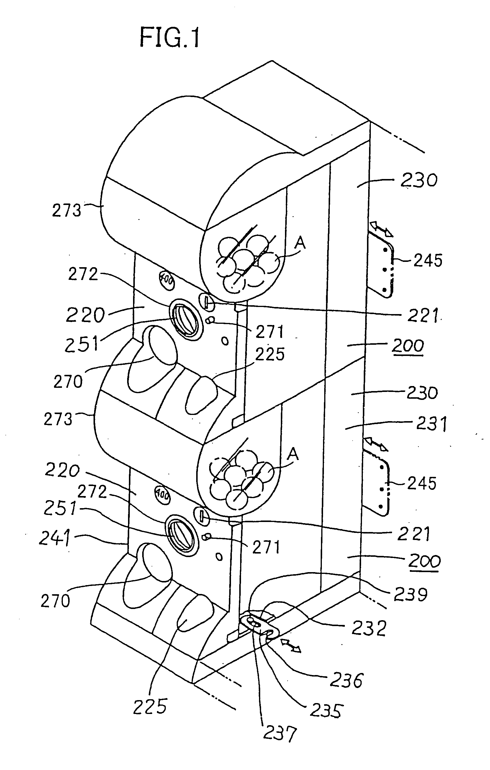
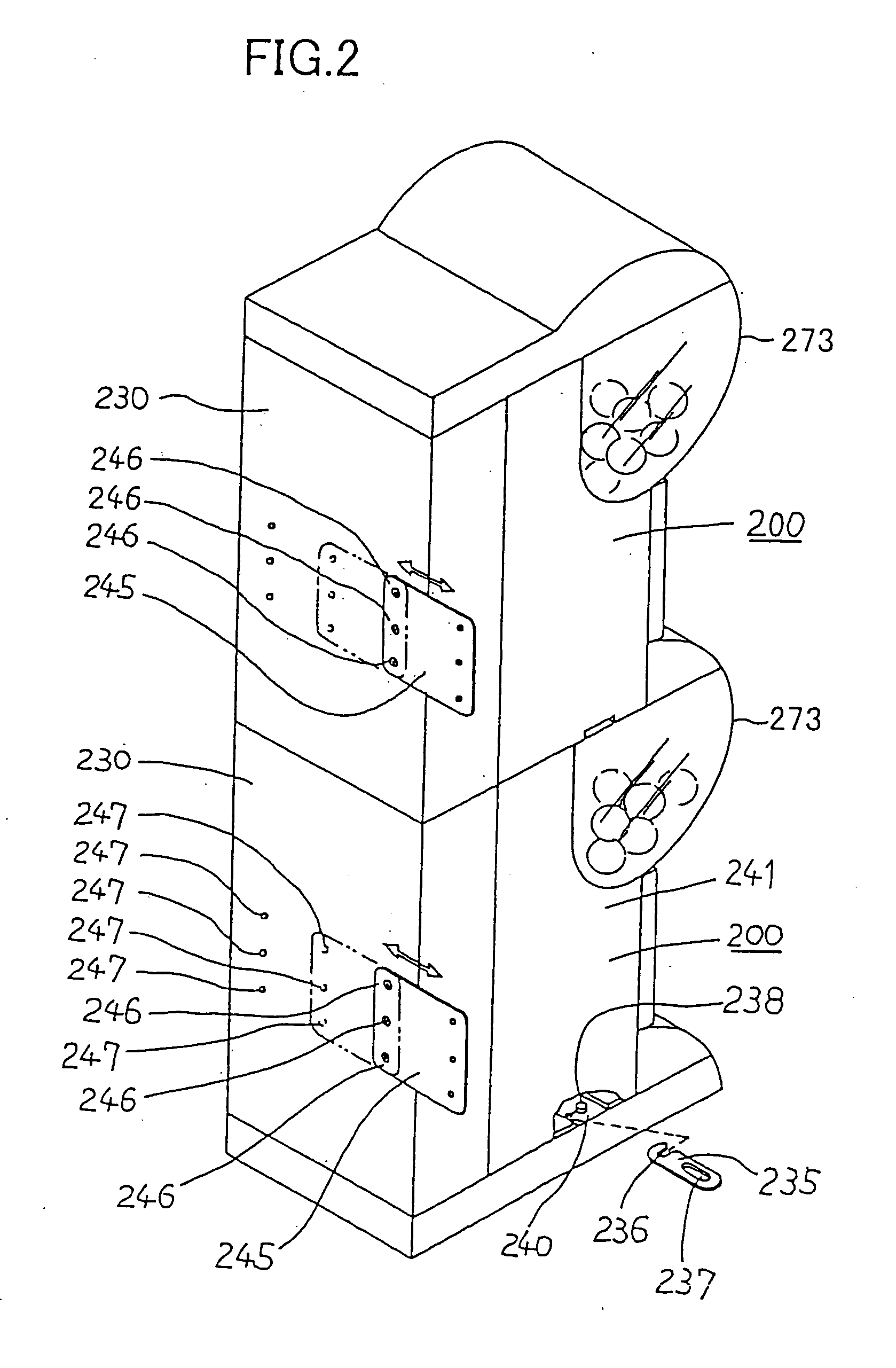
[0039] Referring to FIGS. 1 and 2, now described will be a manual vending machine that has a preferred embodiment of a coin detection apparatus according to the present invention. FIG. 1 is an anterior perspective view showing the manual vending machine that has the embodiment of the coin detection built in, FIG. 2 is a posterior perspective view showing the manual vending machine that has the coin detection apparatus built in, and FIG. 3 is a vertical sectional view illustrating an inside configuration of the same.

[0040] In FIGS. 1 and 2, by way of example only, there can be seen a vertical twin model of vending machine modules 200 where one module stacked over another. The upper module 200 has a box-shaped cabinet 230 that is comprised of almost planar rear, lateral, and bottom faces while the lower module 200 also has a box shaped cabinet 230 that is comprised of almost planar top, rear, lateral, and bottom faces. The upper module 200...


PUM


Abstract

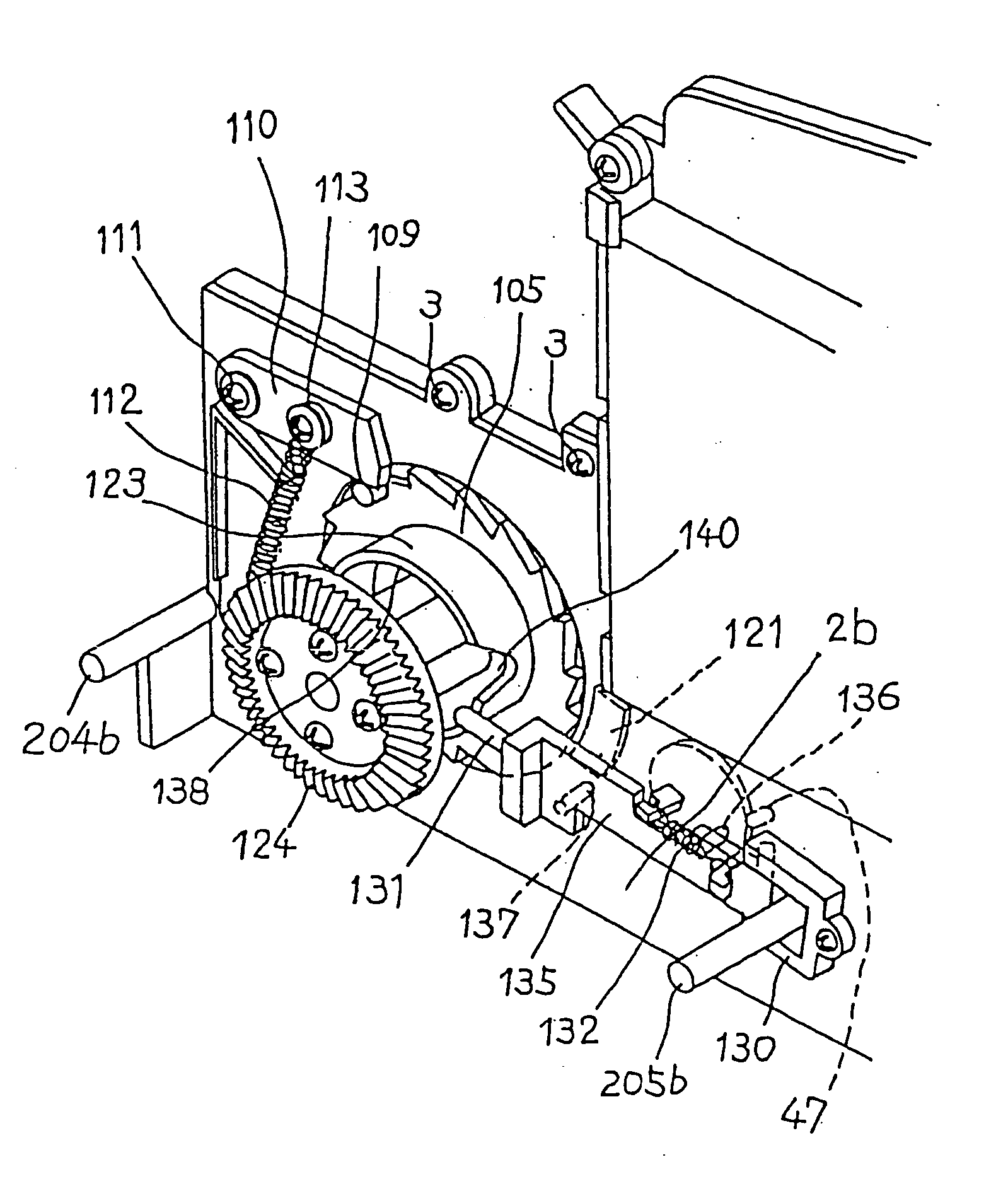
The present invention is directed to a coin detection apparatus that is specially designed to avoid coins' sticking in a coin passage and that is capable of distributing an item to a customer only when a predetermined number of valid coins are paid. Coins (C) deposited by the customer are kept in a coin shoot (13). The coins (C) stand upright on a floor plate (20) that forms a part of the coin shoot (13). The floor plate (20) is urged by a spring member to protrude into the coin shoot (13). As a rotary disk (100) rotates, one end (119) of a recessed portion (120) defined in the rotary disk (100) leans on the floor plate (20) against elastic force of the spring member to make the floor plate (20) tilt. Subsequently, recessed edge of the rotary disk (100) continues to tilt the floor plate (20). As the other end 118 of the recessed portion (120) reaches the floor plate (20), the floor plate (20) is disengaged from the rotary disk (100). Tilt of the floor plate (20) causes the coins (C) to be evacuated from the floor plate (20), and the coins fall direction into a coin drop.

Description

FIELD OF THE INVENTION [0001] The present invention relates to a vending machine that stores lots of packaged commercial items such as toys and distributes them, and more particularly, it relates to a manual vending machine of which rotational handle is turned by a customer to distribute and vend an item contained in the machine. Also, the present invention is directed to a coin detection apparatus that is installed in such a manual vending machine, and it enables the rotational handle to turn if prescribed numbers of specified coins are deposited but, if not, it does not permit the rotational handle to turn. BACKGROUND ART [0002] These days, customers who want to purchase toys have often got toys packaged in containers such as capsules from manual vending machines. Such manual vending machines usually distribute products on the one-machine-one-item or one-machine-two-item basis for predetermined prices, and recently a wider variety of toys have possibly been purchased from the vend...

Claims


Application Information

Patent Timeline
Patent Type & Authority Applications(United States)
IPC IPC(8): G07D5/02G07F5/02G07F5/20
CPCG07D5/02G07F5/20G07F5/02
Inventor NAKASHIMA, KOUJINAKANISHI, YASUYUKI
Owner BANDAI CO LTD
Learn More