

Liquid crystal lens element and optical head device
a liquid crystal lens and optical head technology, applied in the field of liquid crystal lens elements and optical head devices, can solve the problems of writing error, writing error, and the size of the optical head device b>100/b> becoming larger, and achieve the effects of low voltage driving, stable operation, and reduced thickness of liquid crystal layer
- Summary
- Abstract
- Description
- Claims
- Application Information
AI Technical Summary
Benefits of technology
Problems solved by technology
Method used
Image

Examples
first embodiment
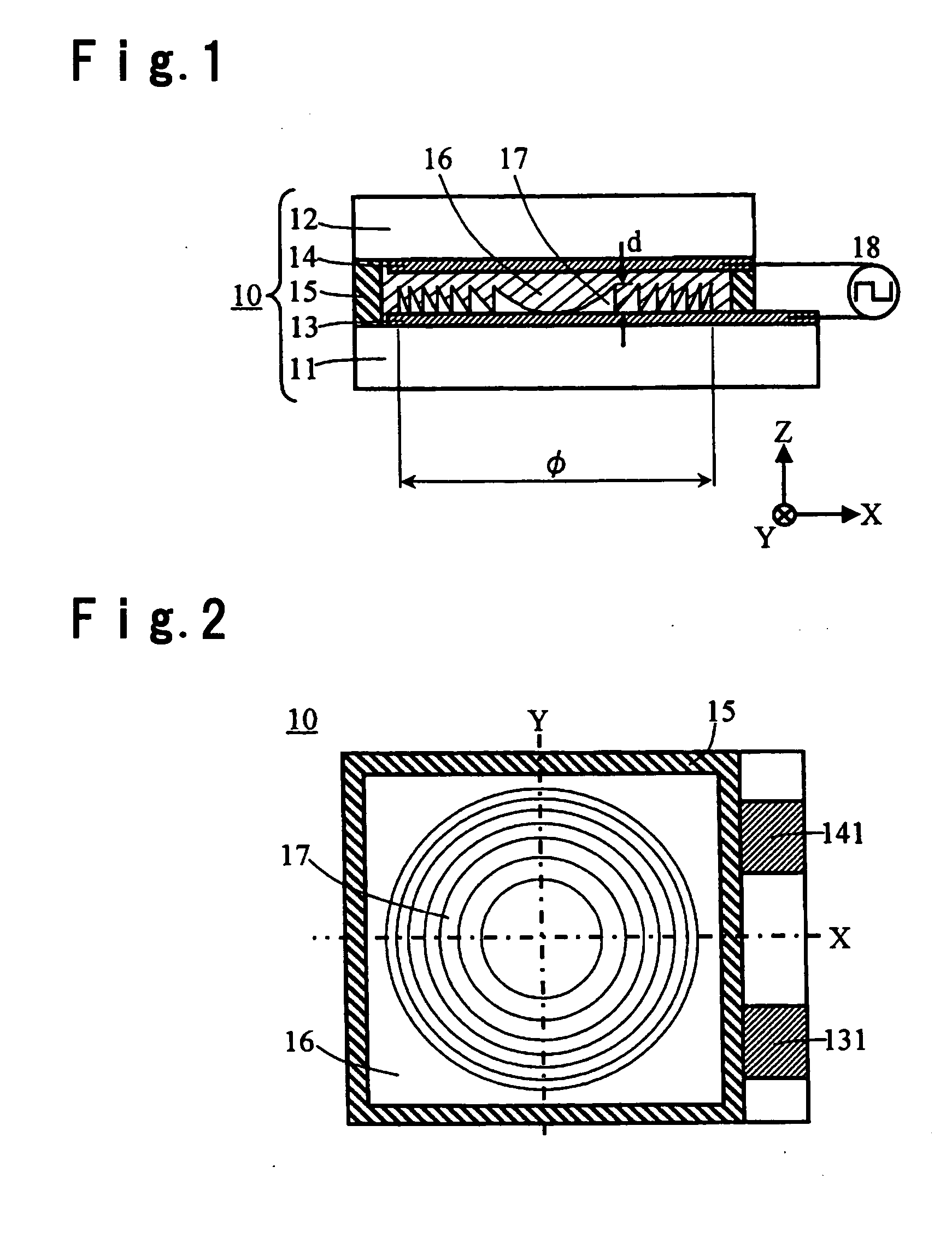
[0106] An example of the construction of a liquid crystal lens element 10 according to a first embodiment of the present invention, is described in detail with reference to a cross-sectional view shown in FIG. 1 and a plan view shown in FIG. 2.
[0107] The liquid crystal lens element 10 according to this embodiment comprises transparent substrates 11 and 12, transparent electrodes 13 and 14, a seal 15, a liquid crystal (liquid crystal layer) 16, a concave-convex portion 17 and an AC power source 18.
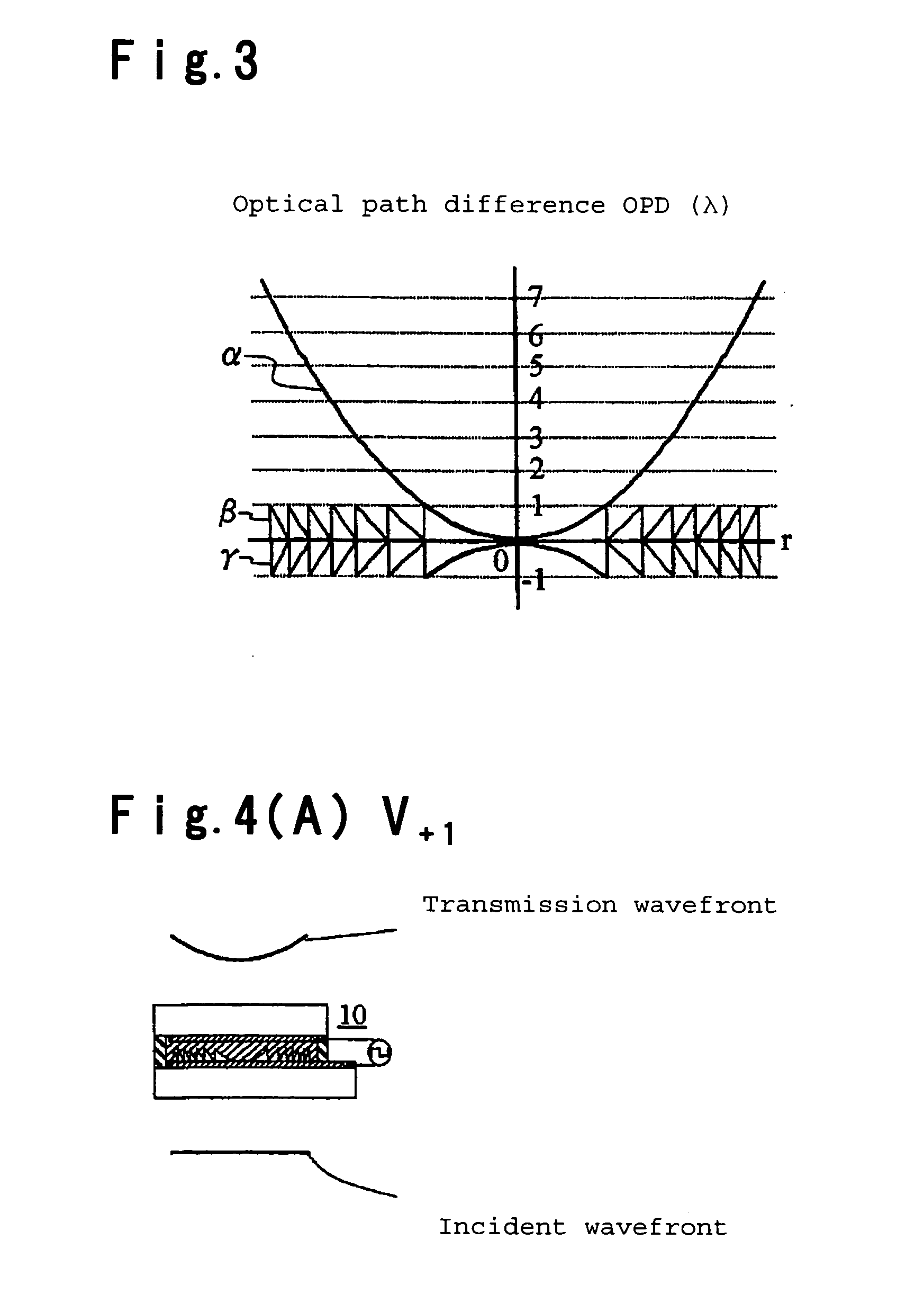
[0108] Among these, the concave-convex portion 17 is, for example, made of a uniform-refractive-index transparent material having a refractive index ns in this embodiment, and the concave-convex portion 17 has a cross-section of a saw-tooth shape or a saw-tooth shape approximated by steps, and has a rotational symmetry about an optical axis (Z axis) of incident light in a region of effective diameter φ. Here, the concave-convex portion 17 preferably has a Fresnel lens shape having the dep...
second embodiment
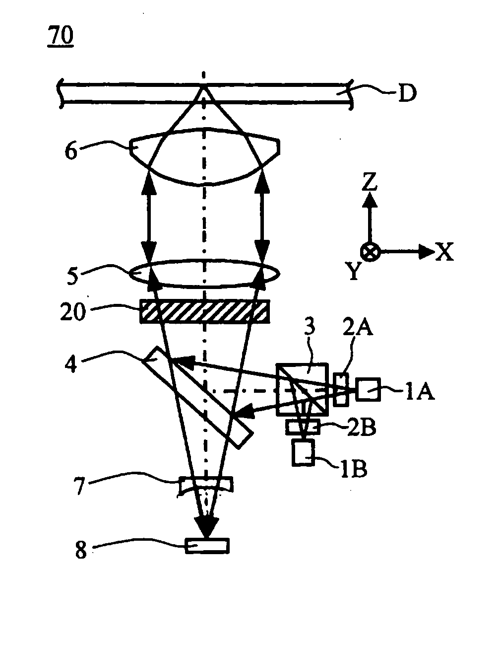
[0169] Then, a liquid crystal lens element 20 according to the second embodiment of the present invention, is described with reference to FIG. 6. Here, in this embodiment, the same components as those of the first embodiment, are designated as the same reference numerals to avoid duplication of explanation.
[0170] The liquid crystal lens element 20 of this embodiment has a construction that in the liquid crystal lens element 10 according to the first embodiment, a phase plate 22 and a transparent substrate 21 are further added. Namely, in the liquid crystal lens element 20, a phase plate 22 made of a birefringent material is sandwiched between a surface of the transparent substrate 12 opposite from a surface on which the transparent electrode 14 is formed, and a transparent substrate 21, to be integrated.
[0171] As the phase plate 22, a birefringent material film produced by drawing an organic film such as a polycarbonate and thus having a slow phase axis in the drawing direction, i...
third embodiment
[0174] Then, a liquid crystal lens element 30 according to a third embodiment of the present invention, is described with reference to FIG. 7. Here, in this embodiment, components in common with those of the first embodiment are designated as the same reference numerals to avoid duplication of explanations.
[0175] The liquid crystal lens element 30 of this example has a construction that two liquid crystal lens elements 10 according to the first embodiment, are laminated in a vertical direction so that their concave-convex portions 17 are opposed to each other (here, they share the transparent substrate 11), and comprises as main components a first liquid crystal lens element 10A, a second lens element 10B and an AC power source 18 for applying AC voltage to these elements.
[0176] Namely, the liquid crystal lens element 30 comprises in the first liquid crystal lens element 10A, two transparent substrates 11 and 12A, transparent electrodes 13A and 14A formed on these transparent subs...
PUM
| Property | Measurement | Unit |
|---|---|---|
| wavelength band | aaaaa | aaaaa |
| thick | aaaaa | aaaaa |
| thicknesses | aaaaa | aaaaa |
Abstract
Description
Claims
Application Information