Electrical circuit arrangement for a power tool

a technology of electric circuit and power tool, which is applied in the direction of electrical apparatus, control systems, dynamo-electric machines, etc., can solve the problems of not always being able to provide the degree of heat dissipation desired, corresponding adverse effects, etc., and achieves the effect of less power, simple and cost-effective, and less power

Inactive Publication Date: 2006-12-28
MARQUARDT GMBH SCHLOSSTRASSE 16 7201 RIETHEIM-WEILHEIM 1 WEST GERMANY
View PDF16 Cites 14 Cited by
  • Summary
  • Abstract
  • Description
  • Claims
  • Application Information

AI Technical Summary

Benefits of technology

[0014] The particular advantages achieved with the invention include the ability to obtain a closed closed-loop control circuit to protect the circuit arrangement, and in particular the electronic power system in a power tool switch, against overheating. Nev...

Problems solved by technology

It has become apparent, however, that it is not always possible to provide the degree of heat dissipation desired.
In particular, in electric switches for high-power power tools, the circuit arrangement provided for performing open-loop control of the rotational speed or for switchi...

Method used


Image

  • Electrical circuit arrangement for a power tool
  • Electrical circuit arrangement for a power tool
  • Electrical circuit arrangement for a power tool

Examples


Embodiment Construction

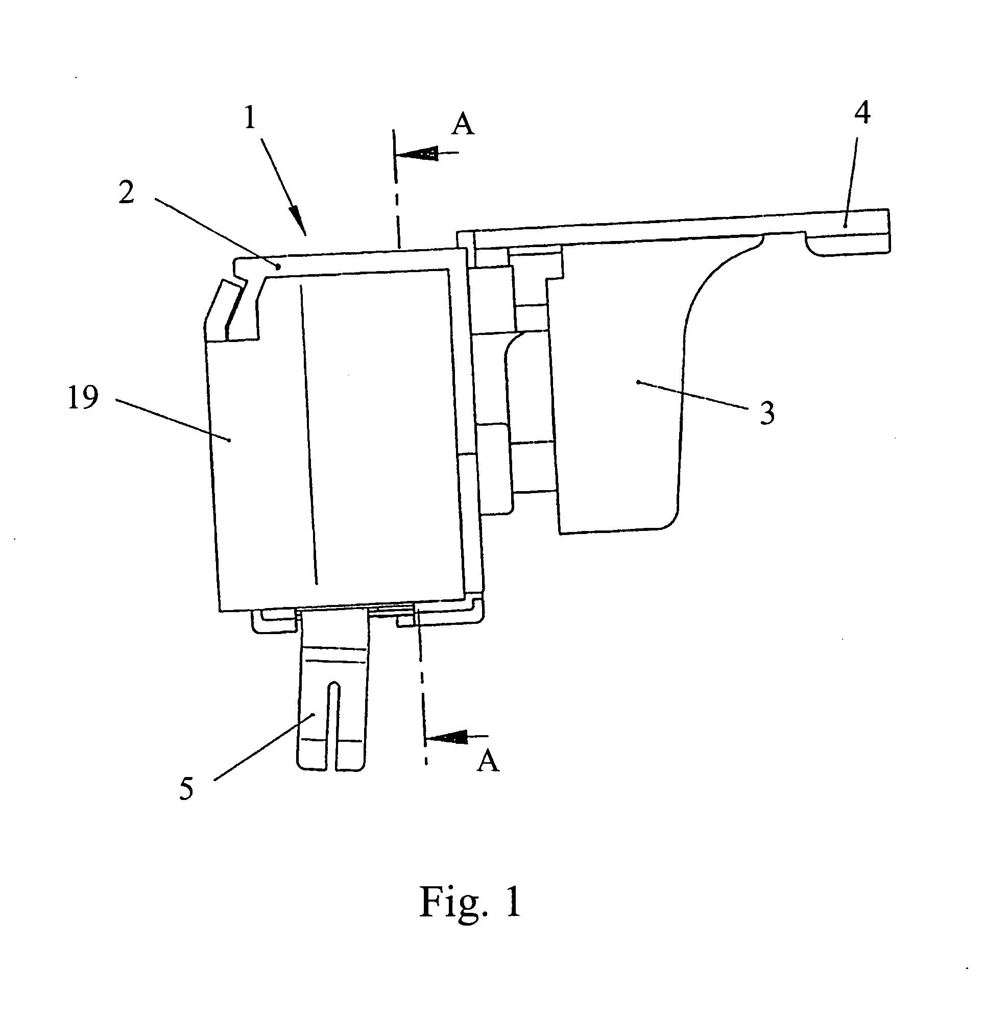
[0019]FIG. 1 shows an electrical switch 1 which is to be used for a power tool with an electric motor, to be precise in particular for an accumulator-type power tool which is operated with DC voltage. The switch 1 has a housing 2, an activation member 3, which is shown as a pushbutton switch and which is moveably arranged on the housing 2 for the manual activation of the power tool by the user, an activation element 4, which is shown as a switchover lever for switching over the right-left running direction of the power tool, and connecting terminals 5 which are arranged on the housing 2 and provide an electrical connection to the accumulator. Of course, given the appropriate configuration, which will also be described briefly below, such a switch 1 can also be used for a mains power tool which is operated with alternating voltage.

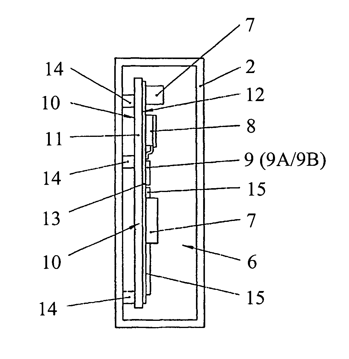
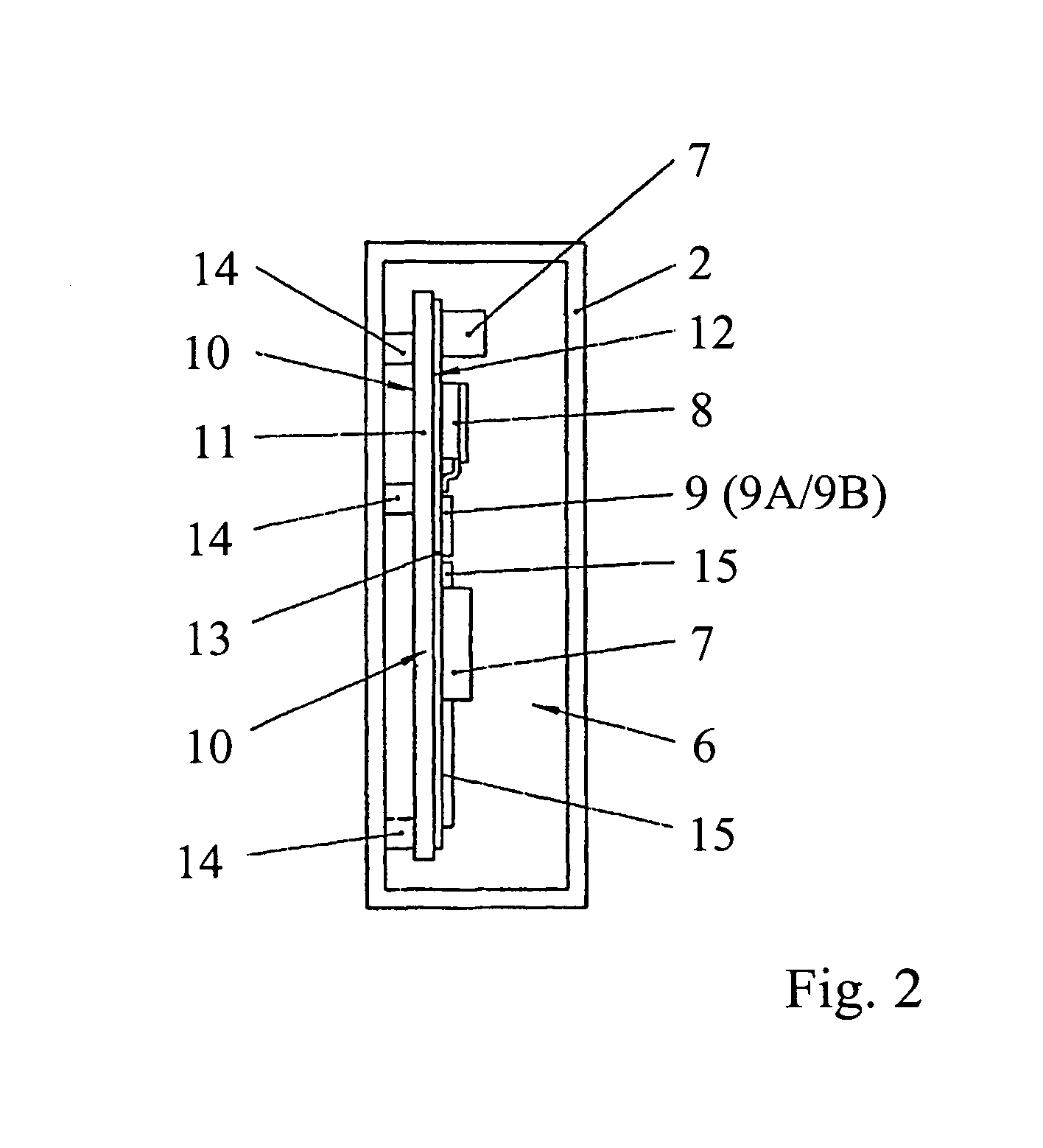
[0020] As shown schematically in FIG. 2, an electrical circuit arrangement 6 is arranged in the housing 2. The electrical circuit arrangement 6 is embodie...


PUM


Abstract

A circuit arrangement is provided, including at least one heat-generating power component and means for monitoring the temperature of the circuit arrangement. When a preset limiting temperature is reached, the means for monitoring the temperature reduces the power of the load using the power component by reducing the load current flowing through the power component. An electric switch including such a circuit arrangement is also provided.

Description

CROSS REFERENCE TO RELATED APPLICATIONS [0001] This application is a continuation of International Application No. PCT / EP2005 / 002276, having a filing date of Mar. 4, 2005, which designated the United States, and claims the benefit under 37 USC §119(a)-(d) of German Application No. 10 2004 010 737.8, filed Mar. 5, 2004, the entireties of which are incorporated herein by reference.FIELD OF THE INVENTION [0002] The present invention relates to an electrical circuit arrangement. BACKGROUND OF THE INVENTION [0003] Electrical circuit arrangements are used for open-loop and / or closed-loop control of power which is output by a load. The load can be, for example, an electric motor wherein the circuit arrangement is used for open-loop and / or closed-loop control of the rotational speed and / or torque of the electric motor. [0004] Such an electrical circuit arrangement is composed of electrical and / or electronic components. The components include at least one heat-generating power component such...

Claims


Application Information

Patent Timeline
IPC IPC(8): H02P7/00H03K17/08H03K17/082
CPCH03K2017/0806H03K17/0822
Inventor BROGHAMMER, PETER
Owner MARQUARDT GMBH SCHLOSSTRASSE 16 7201 RIETHEIM-WEILHEIM 1 WEST GERMANY
Why Eureka
Try Eureka