Multi-phase flow measurement system having a fluid separator

a technology of fluid separator and flow measurement system, which is applied in the direction of liquid/fluent solid measurement, volume metering, instruments, etc., can solve the problems of increasing the size of the already bulky separator device, and affecting the accuracy of the measuremen

Active Publication Date: 2007-01-11
EXPRO METERS
View PDF3 Cites 55 Cited by
  • Summary
  • Abstract
  • Description
  • Claims
  • Application Information

AI Technical Summary

Problems solved by technology

Unfortunately however, current gas / liquid separator devices tend to be large, bulky and inefficient devices that are expensive to implement and operate.
This type of sensitive equipment is expensive to maintain.
This tends to increase the size of the already bulky separator devices.

Method used


Image

  • Multi-phase flow measurement system having a fluid separator
  • Multi-phase flow measurement system having a fluid separator
  • Multi-phase flow measurement system having a fluid separator

Examples


first embodiment

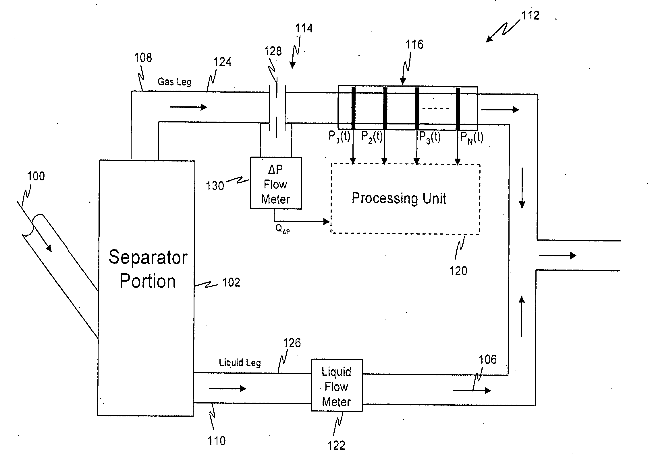
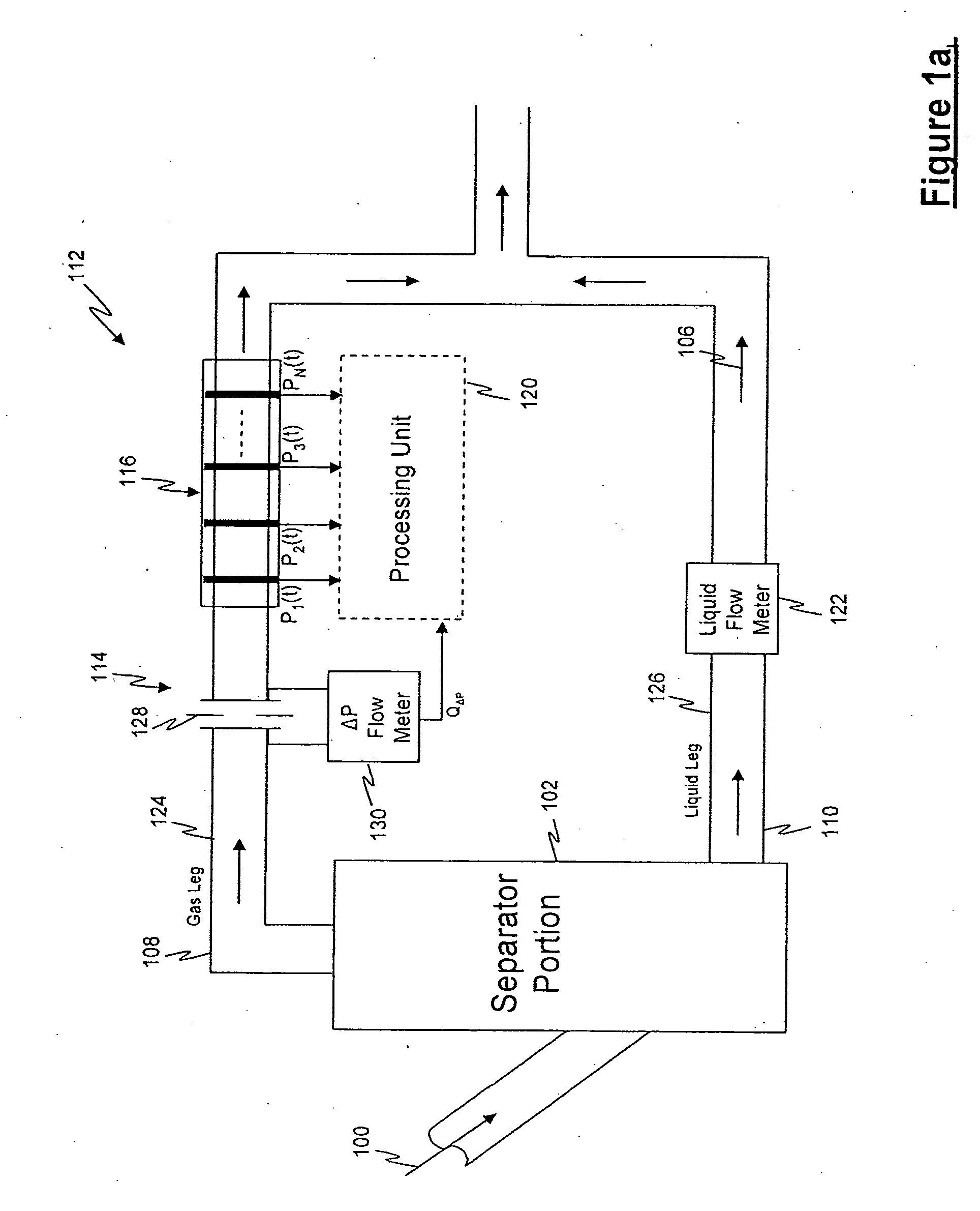
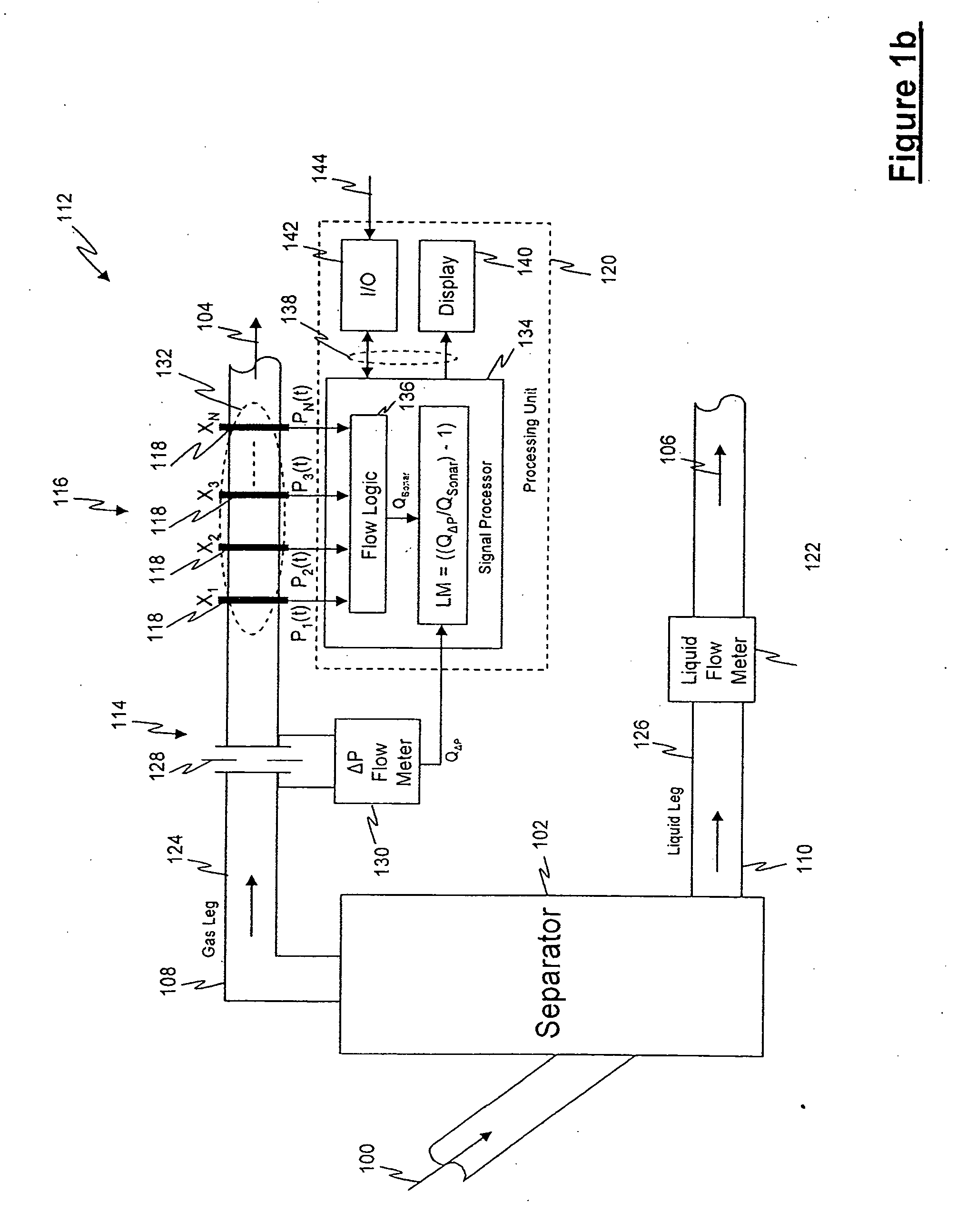
[0093] Referring to FIG. 12, the multiphase meter 300 having a separator portion 102 in accordance with the present invention is illustrated for providing outputs that include the phase fraction of each of the phases of the fluid flow 100 and the volumetric flow rate of each of the phases. The phase of the fluid 100 may comprise a gas-liquid mixture or a liquid-liquid-gas mixture (such as oil, gas and water) in the form of a wet gas mixture. The flow meter 300 includes a bypass pipe 302 for separating the wet gas mixture into a liquid flow 106 and a gas flow 104, wherein the liquid portion 106 of the mixture 100 flows through the bypass pipe 302 and the gas portion 104 of the mixture 100 (which may include some liquid droplets or mist) flows through a primary pipe 304. It should be appreciated that the bypass pipe 302 may include a smaller cross-sectional area than the primary pipe 304 in order to accommodate the lesser amount of liquid in the flow 100. Similar to that described her...

second embodiment

[0094] Referring to FIG. 13, a flow meter 350 is shown and is similar to that illustrated in FIG. 12, with the exception that a second DP meter 352 is provided after the recombination of the separated flows 104,106. The second DP meter 352 may be similar to the DP meter 308 on the primary pipe 304, such as an orifice plate, cone meter (e.g., venturi), or similar device to provide a pressure difference across the device. Alternatively, the DP meter 352 may be different which will provide additional information to characterize and measure the flow 100. The second or added DP meter 352 may provide a means to measure and characterize the flow 106 passing through the bypass pipe 302. As shown in FIG. 14, the wetness of the fluid can be measured in the primary pipe 304 and the output pipe 124 after the flows 104,106 are recombined. This difference in wetness at these locations enables measurement of the phase fraction of the fluid flow 100.

third embodiment

[0095] Referring to FIG. 15, a flow meter 400 is illustrated, wherein the flow meter 400 includes a flow meter 402 disposed to directly measure the flow rate of the liquid flowing within the by pass pipe 302. The flow meter 402 may be any flow meter known in the art. The flow meter 400 provides for a more direct measurement of the flow 106 through the bypass pipe 302.


PUM

PropertyMeasurementUnit
pressureaaaaaaaaaa
constant-currentaaaaaaaaaa
densityaaaaaaaaaa

Abstract

An apparatus for determining a characteristic of a fluid flow within a pipe is provided, wherein the apparatus includes a separating device for separating the fluid into a gas component and a liquid component and directing the gas component to flow within a gas leg portion of the pipe and the liquid component to flow within a liquid portion of the pipe. The apparatus includes a gas leg portion metering device for generating gas component data and a liquid leg portion metering device for generating liquid component data. Moreover, the apparatus includes a processing device communicated with at least one of the gas leg portion metering device and the liquid leg portion metering device, the processing device being configured to receive and process at least one of the gas component data and the liquid component data to generate fluid flow data responsive to a fluid flow characteristic.

Description

CROSS-REFERENCE TO RELATED PATENT APPLICATIONS [0001] This application claims the benefit of U.S. Provisional Patent Application No. 60 / 760,845 (Atty. Docket No. CC-0845) filed Jan. 19, 2006, U.S. Provisional Patent Application No. 60 / 759,159 (Atty. Docket No. CC-0844) filed Jan. 12, 2006; U.S. Provisional Patent Application No. 60 / 758,382 (Atty. Docket No. CC-0843) filed Jan. 11, 2006; U.S. Provisional Patent Application No. 60 / 724,952 (Atty. Docket No. CC-0832) filed Oct. 6, 2005; U.S. Provisional Patent Application No. 60 / 697,479 (Atty. Docket No. CC-0820) filed Jul. 7, 2005, U.S. Provisional Patent Application No. 60 / 762,101 (Atty. Docket No. CC-0846) filed Jan. 24, 2006; U.S. Provisional Patent Application No. 60 / 773,146 (Atty. Docket No. CC-0847) filed Feb. 13, 2006, U.S. Provisional Patent Application No. 60 / 774,706 (Atty. Docket No. CC-0848) filed Feb. 17, 2006, and U.S. Provisional Patent Application No. 60 / ______ (Atty. Docket No. CC-0860) filed Jun. 30, 2006, all of which...

Claims


Application Information

Patent Timeline
Patent Type & Authority Applications(United States)
IPC IPC(8): G01N33/20G01F1/74G01F1/7082
CPCG01F1/36G01F1/7082G01F1/712G01N33/26G01F5/00G01F15/08G01F1/74G01F1/666
Inventor GYSLING, DANIEL L.
Owner EXPRO METERS
Why Eureka
Try Eureka