Method and apparatus for controlling a windrower header flotation system during removal of the header

a technology of flotation system and windrower, which is applied in the field of agricultural windrowers, can solve the problems of not being able to independently adjust the flotation force for each the wide range of mechanical components required to float the header, and the inherently balanced side to side of the header, so as to improve the hydraulic and structural durability of the harvester, reduce the impact of hydraulic and mechanical shock loading, and improve the ride comfort for the operator

Inactive Publication Date: 2007-01-18
CNH IND AMERICA LLC
View PDF39 Cites 2 Cited by
  • Summary
  • Abstract
  • Description
  • Claims
  • Application Information

AI Technical Summary

Benefits of technology

[0014] It is an even still further object of the instant invention to provide a hydraulic header flotation and lift system that reduces hydraulic and mechanical shock loading when raising the header in a less than fully raised position, improving the ride comfort for the operator and improving hydraulic and structural durability of the harvester.
[0015] It is yet another object of this invention to provide an improved hydraulic header lift and flotation system that is durable in construction, inexpensive of manufacture, carefree of maintenance, facile in assemblage, and simple and effective in use.

Problems solved by technology

The structure generally requires numerous components and large extension springs, and it is quite difficult to develop the mechanical components required to float the broad range of header sizes available even requiring different tractors or frames having their own flotation systems designed to meet their own particular header weight requirements.
These machines typically use separate hydraulic cylinders for the lift and flotation functions, and they lack the capability of independently adjusting the flotation force for each side of the header.
Additionally, some headers are not inherently balanced side to side.
Special considerations must be made to float and lift these headers evenly by adding ballast, which can become unreasonably heavy or awkward, or modifying the lift geometry of one side.

Method used


Image

  • Method and apparatus for controlling a windrower header flotation system during removal of the header
  • Method and apparatus for controlling a windrower header flotation system during removal of the header
  • Method and apparatus for controlling a windrower header flotation system during removal of the header

Examples


Embodiment Construction

[0051] Many of the fastening, connection, processes and other means and components utilized in this invention are widely known and used in the field of the invention described, and their exact nature or type is not necessary for an understanding and use of the invention by a person skilled in the art, and they will not therefore be discussed in significant detail. Also, any reference herein to the terms “left” or “right” are used as a matter of mere convenience, and are determined by standing at the rear of the machine facing in its normal direction of travel. Furthermore, the various components shown or described herein for any specific application of this invention can be varied or altered as anticipated by this invention and the practice of a specific application of any element may already by widely known or used in the art by persons skilled in the art and each will likewise not therefore be discussed in significant detail.

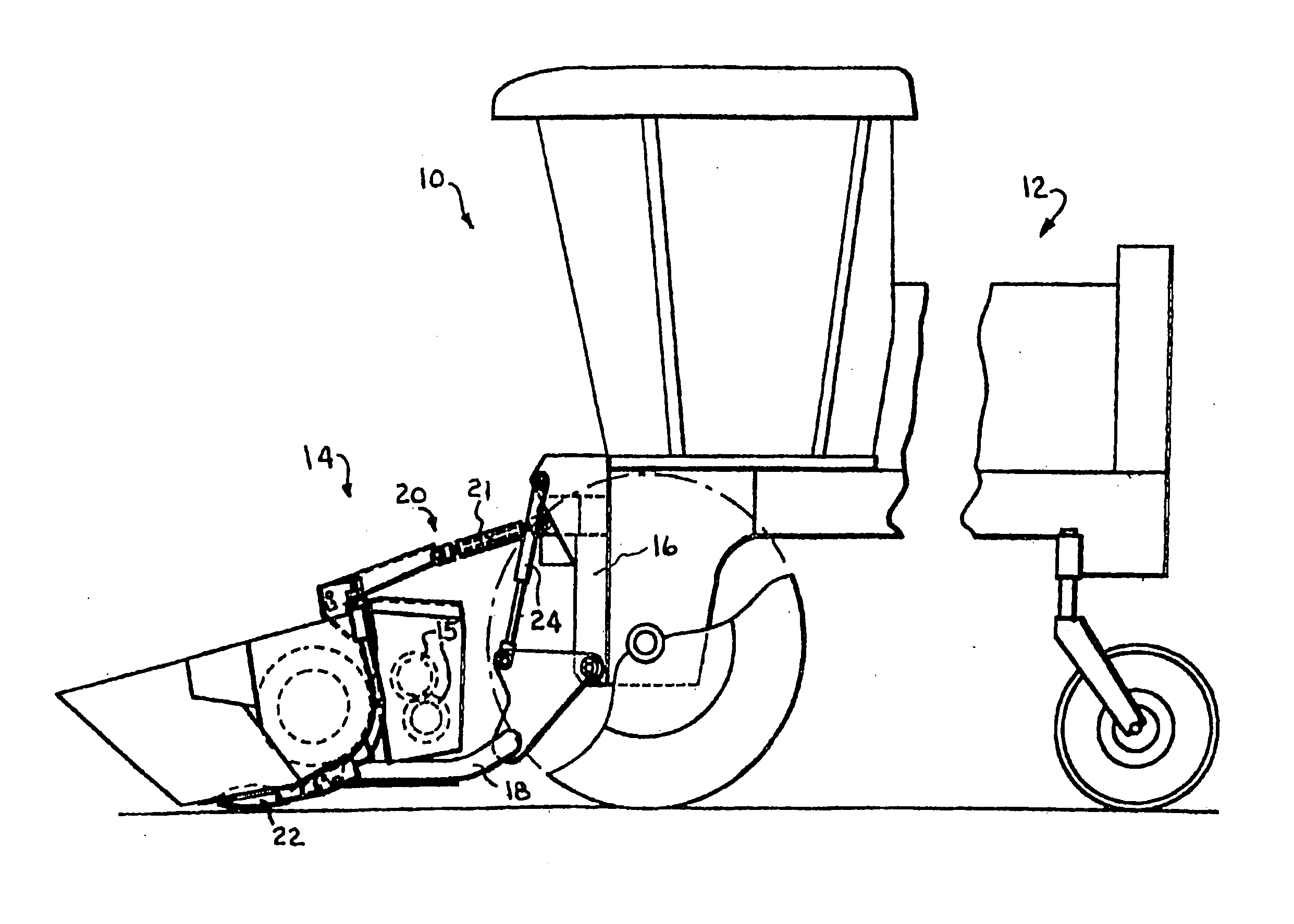
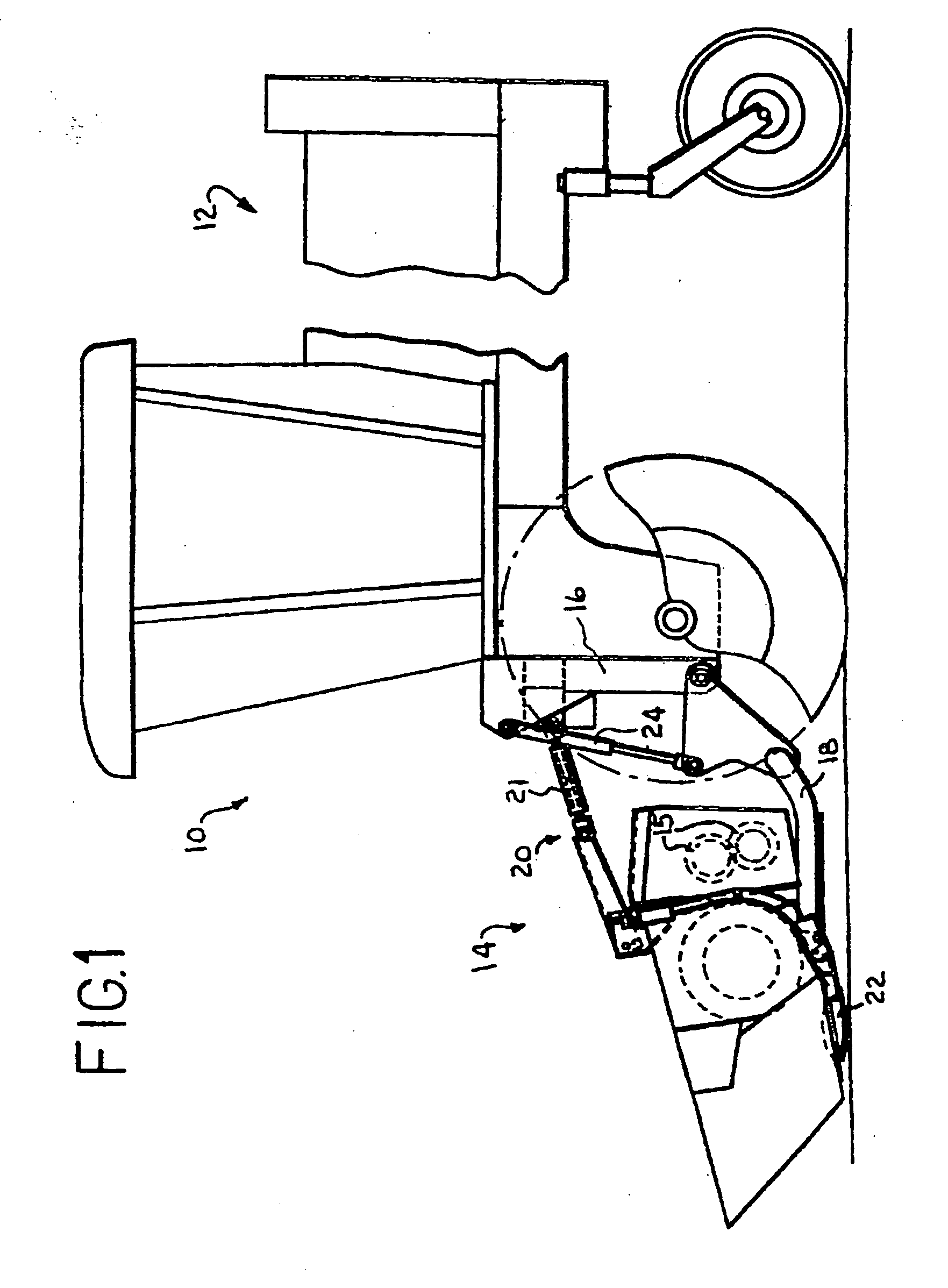
[0052]FIG. 1 shows the present invention utilized in co...


PUM


Abstract

A method and apparatus for controlling the flotation system of an agricultural harvesting machine such as a windrower, wherein the system is programmed to be automatically operable for entering a header remove mode when operating conditions indicate an intent to remove the header, which conditions can be, for instance, the setting or a flotation force value for the system to zero or near zero, and which will automatically exit the header remove mode when conditions indicate an intent to return to normal operation, for instance, when a flotation force is increased to at least a predetermined value.

Description

[0001] This application claims the benefit of U.S. Provisional Application Nos. 60 / 699,271, filed Jul. 14, 2005, and 60 / 699,550, filed Jul. 15, 2005.TECHNICAL FIELD [0002] The present invention relates to agricultural windrowers and, more particularly, to a method embodied in a software program and apparatus for controlling the hydraulics during the removal of a windrower header. BACKGROUND OF THE INVENTION [0003] U.S. Pat. No. 6,901,729, is incorporated herein by reference in its entirety. This patent describes a header flotation system that is referred to as “non-independent”. U.S. Provisional Application Nos. 60 / 699,271, filed Jul. 14, 2005, and 60 / 699,550, filed Jul. 15, 2005, are also incorporated herein by reference in their entirety. [0004] It is the non-independent embodiment that provides the best example of the type of system with which the program of the instant invention can / should be used. [0005] The present invention relates generally to harvesting machines of the type...

Claims


Application Information

Patent Timeline
Patent Type & Authority Applications(United States)
IPC IPC(8): A01D41/14
CPCA01D41/141A01D41/14
Inventor OTTO, DOUGLAS R.FACKLER, ROBERT L.
Owner CNH IND AMERICA LLC
Why Eureka
Try Eureka