

Grid-holding element
- Summary
- Abstract
- Description
- Claims
- Application Information
AI Technical Summary
Benefits of technology
Problems solved by technology
Method used
Image

Examples
Embodiment Construction
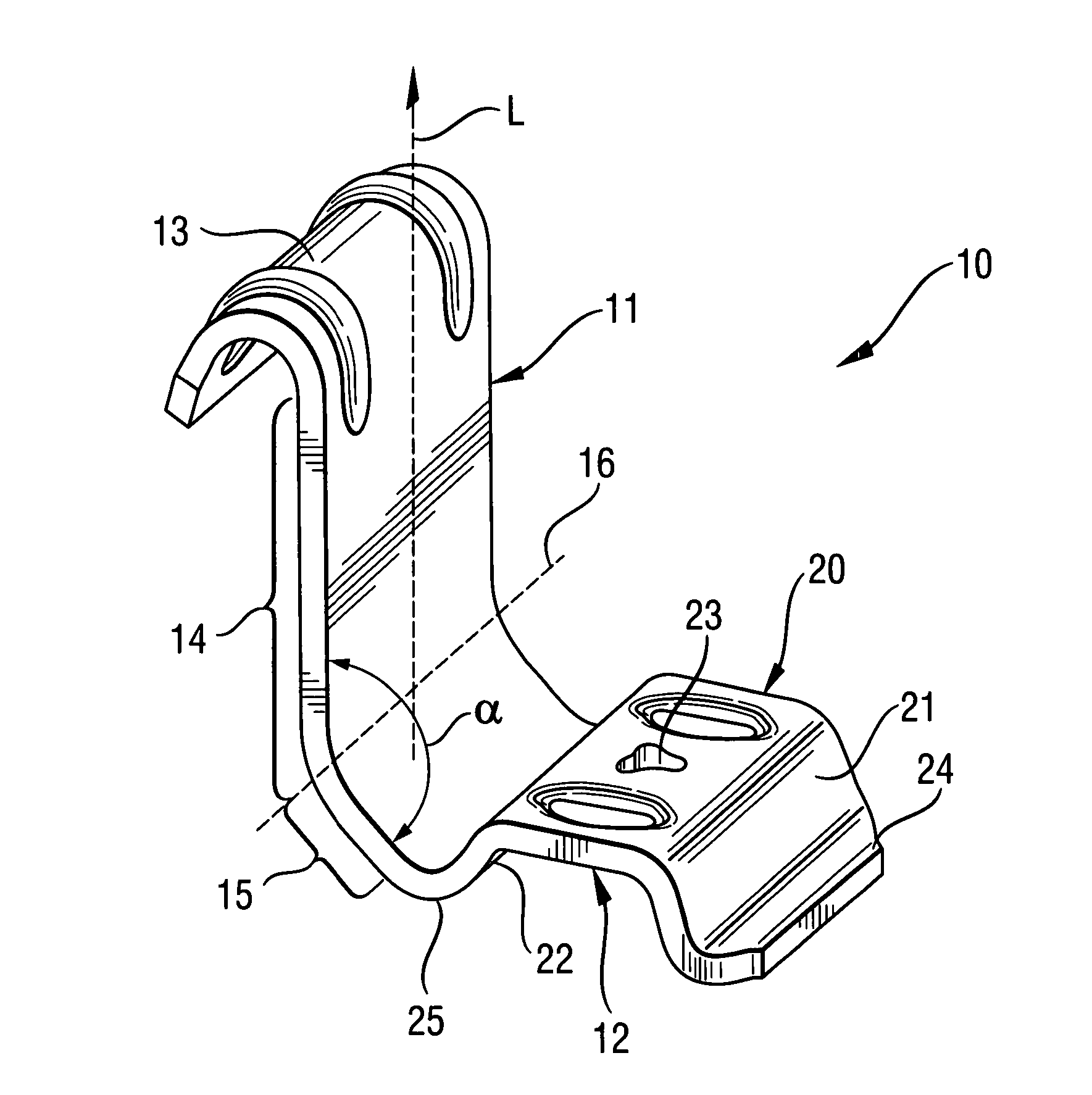
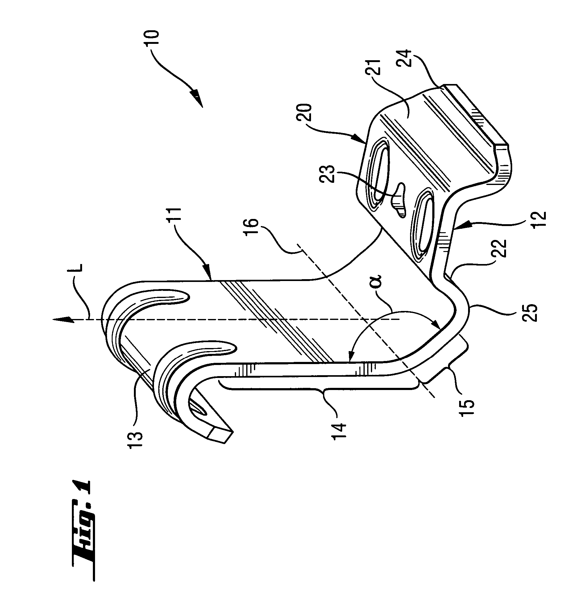
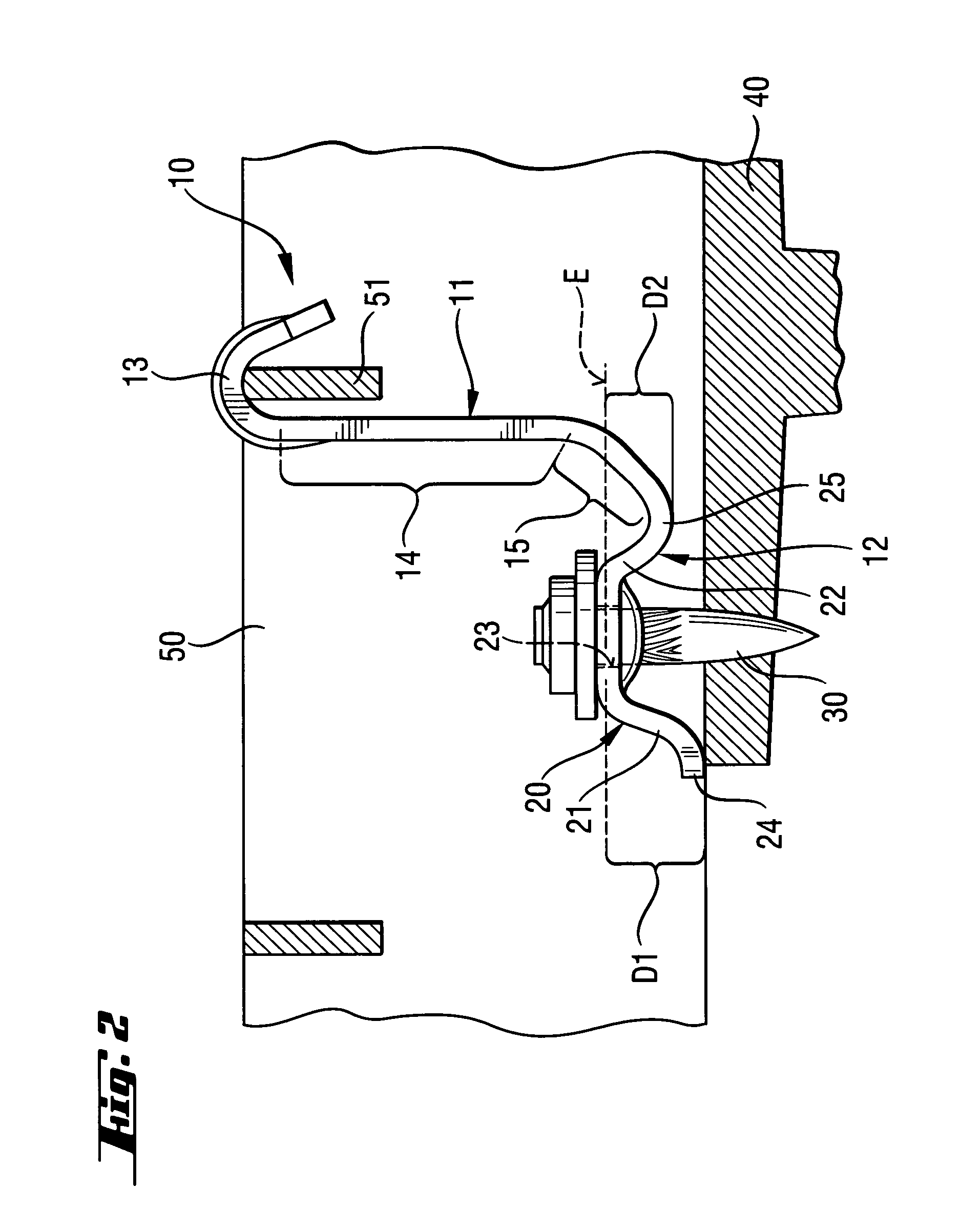
[0019] A grid-holding element 10 according to the present invention, which is shown in FIGS. 1-2, has a first leg 11 and a second leg 12 which are arranged approximately at a right angle to each other. The first leg 11 has a hook-shaped free upper end 13 for engaging around a strut 51 of a grid 50 or another element to-be-secured on a support 40. The first leg 11 further has first and second surface sections 14 and 15 that extend to each other in the initial, not secured position of the holding element 10, at an angle α of about 138°. However, in the embodiment shown in the drawings and having two surface sections 14, 15, a greater or smaller angle α that can vary in a range from 125° to 150° can be provided. The first leg 11 extends substantially in a longitudinal direction L that is directed substantially perpendicular to a bending axis 16 along which both surface sections 14, 15 abut each other.
[0020] The second leg 12 forms a saddle-shaped attachment section 20 that has a throu...
PUM
 Abstract
Description
Claims
Application Information