Self-collimation zero-phase-shift transmission method based on photonic crystal

A photonic crystal and self-collimation technology, which is applied in the fields of optoelectronics and optical communication, can solve the problems of sharp changes in the emission direction of zero-phase-shift electromagnetic waves, uncertain transmission directions, and incompatibility of targets, and achieves the effect of self-collimation and zero-phase-shift transmission.

Active Publication Date: 2016-01-20
UNIVERSITY OF CHINESE ACADEMY OF SCIENCES
View PDF2 Cites 0 Cited by
  • Summary
  • Abstract
  • Description
  • Claims
  • Application Information

AI Technical Summary

Problems solved by technology

However, the refraction direction of the electromagnetic wave in this method is very sensitive to the incident direction of the electromagnetic wave, and a small change in the incident angle may cause a drastic change in the outgoing direction of the zero-phase-shift electromagnetic wave, which has problems in practical operation and uncertain transmission direction.
If traditional autocollimator modulation is used, phase shift will inevitably be introduced, which is inconsistent with the goal of zero phase shift transmission of electromagnetic waves

Method used


Image

  • Self-collimation zero-phase-shift transmission method based on photonic crystal
  • Self-collimation zero-phase-shift transmission method based on photonic crystal
  • Self-collimation zero-phase-shift transmission method based on photonic crystal

Examples


Embodiment 1

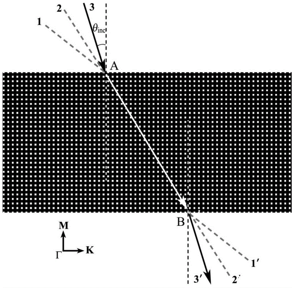
[0034] Choose a two-dimensional photonic crystal, set the lattice constant of the photonic crystal as a, such as figure 1 As shown, the air (dielectric constant ε = 1) in the Al 2 o 3 The dielectric background (purity>99%, ε=10) is arranged periodically according to the square lattice structure, the side length of the air column is 0.4a, and the filling ratio is 83.6%, and the photonic crystal plate is obtained. The photonic crystal plate is cut along the ΓK direction. The width of the crystal plate along the ΓM direction is determined by the distance that the electromagnetic wave propagates in the photonic crystal plate. The length of the photonic crystal plate is required to ensure that the electromagnetic wave does not exit from the side of the crystal plate.

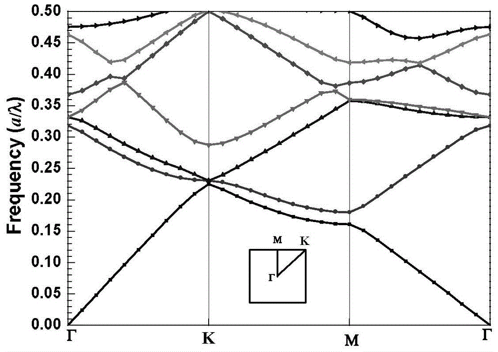
[0035] from figure 2 It can be seen from the shown energy band structure that the photonic crystal plate does not have a full band gap in the TM polarization state.

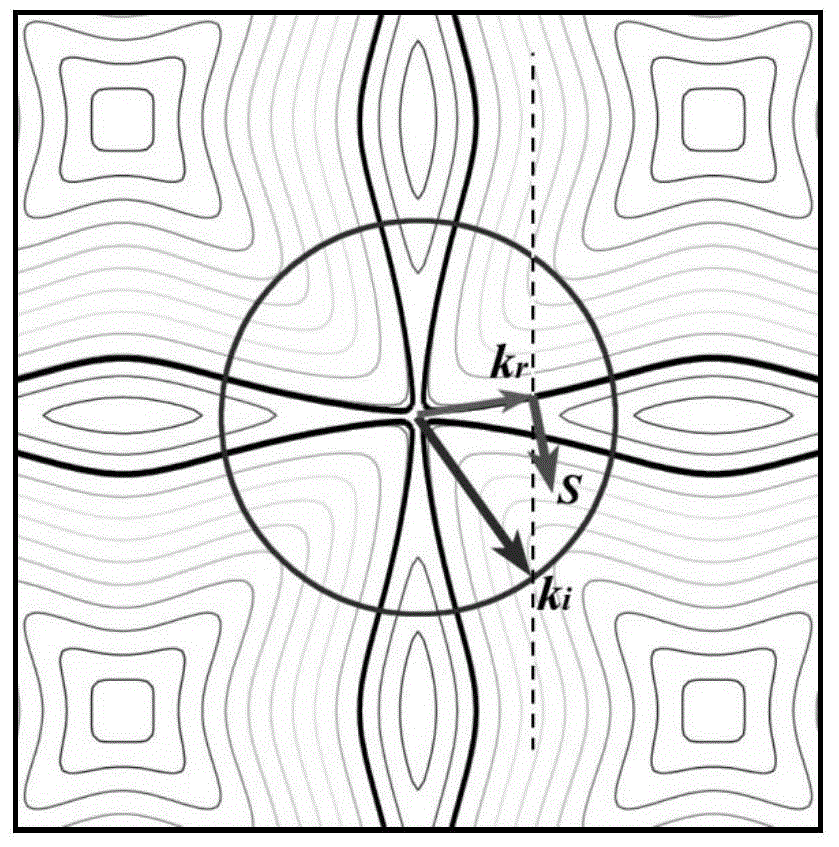
[0036] image 3 The distribution of equifreq...

Embodiment 2

[0046] With embodiment 1, radius r=0.5a cross-sectional shape is the Al of circle 2 o 3 The rods (dielectric constant ε=10) are periodically arranged in the air (n=1) according to the square lattice structure, and the photonic crystal plate is obtained. Cut the photonic crystal plate along the ΓM direction, when the TM polarized electromagnetic wave with a relative frequency of ω=0.335 is 10°inc When the air is incident on the photonic crystal plate at any angle within the incident angle range of <60°, a refracted wave with a refraction angle of 13° can be excited in the photonic crystal plate along the ΓM direction at the incident interface, and its equiphase plane is parallel to the propagation direction, realizing The self-collimated zero-phase-shift transmission of electromagnetic waves in the photonic crystal plate is achieved.

Embodiment 3

[0048] Same as in Example 1, the circular air columns are arranged periodically on the Al 2 o 3 In the dielectric background, the radius of the air column is 0.25a, ​​and the filling ratio is 80.4%, resulting in a photonic crystal plate. Cut the photonic crystal plate along the ΓM direction, when the TM polarized electromagnetic wave with a relative frequency of ω=0.3345 is 10°inc When the air is incident on the photonic crystal plate at any angle within the incident angle range of <60°, a refracted wave with a refraction angle of 11.5° can be excited in the photonic crystal plate along the ΓM direction at the incident interface, and its equiphase plane is parallel to the propagation direction, realizing The self-collimated zero-phase-shift transmission of electromagnetic waves in the photonic crystal plate is achieved.

[0049] When the radius of the air column is changed or another medium is used as the medium background, the operating frequency (wavelength) of the self-col...


PUM


Abstract

The invention discloses an electromagnetic wave auto-collimation zero phase shift transmission method based on photonic crystals. A photonic crystal board is formed by periodically arranging homogeneous dielectric substances in space, and the incident plane and the emergent plane of the photonic crystal board are formed by being cut in the space symmetry axis direction of the photonic crystals. When electromagnetic waves with specific wave lengths are injected into the photonic crystal board at random angles within a certain incident angle range, refraction occurs on an interface, the refraction direction of the electromagnetic waves is unchanged through spatial modulation of a photonic crystal periodic structure, equiphase surfaces of the electromagnetic waves can be parallel with the energy flow direction, zero phase shift transmission is maintained in the fixed propagation direction, and therefore auto-collimation zero phase shift transmission of the electromagnetic waves in the photonic crystals is achieved. On the basis of the electromagnetic wave basic theory and the photonic crystal energy band modulation theory, the invention provides a brand new method for achieving auto-collimation zero phase shift transmission of the electromagnetic waves based on photonic crystals. Accordingly, processing techniques are simplified, production cost is reduced, use flexibility is improved, and the method has important academic significances and application value.

Description

technical field [0001] The invention belongs to the technical fields of optical communication and optoelectronics, and relates to a method for self-collimation and zero-phase-shift transmission of electromagnetic waves. Background technique [0002] As a new type of artificial dielectric material, all-dielectric-based photonic crystals have become a very popular research field in physics, photonics, electromagnetic field theory, material science, and nanotechnology due to their excellent performance and potential scientific value. The periodic structure of photonic crystals can endow the material with unique anomalous optical properties. By modulating its spatial structure and dielectric properties, it can control the transmission properties of electromagnetic waves or light waves in a large range. It is considered to be the future Photonic crystal devices are a breakthrough towards practicality in the field of optical information. [0003] The phase of the electromagnetic ...

Claims


Application Information

Patent Timeline
Patent Type & Authority Patents(China)
IPC IPC(8): G02B6/122
Inventor 董国艳
Owner UNIVERSITY OF CHINESE ACADEMY OF SCIENCES
Why Eureka
Try Eureka