Auto-collimation zero phase shift transmission method based on photonic crystals
A photonic crystal and self-collimation technology, applied in the fields of optical communication and optoelectronics, can solve the problems of sharp changes in the emission direction of zero-phase-shift electromagnetic waves, inconsistent targets, and uncertain transmission directions, and achieve the effect of self-collimation and zero-phase-shift transmission.
- Summary
- Abstract
- Description
- Claims
- Application Information
AI Technical Summary
Problems solved by technology
Method used
Image
Examples
Embodiment 1
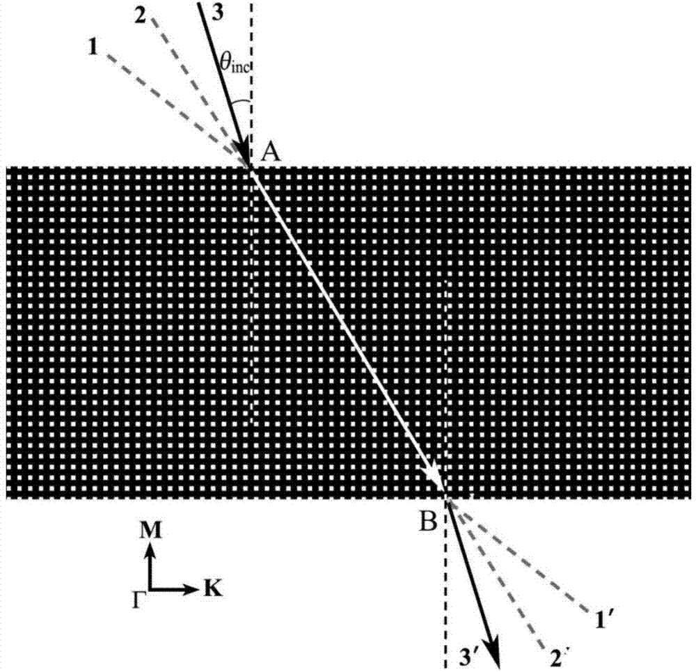
[0034] Choose a two-dimensional photonic crystal, set the lattice constant of the photonic crystal as a, such as figure 1 As shown, the air (dielectric constant ε = 1) in the Al 2 o 3 The dielectric background (purity>99%, ε=10) is arranged periodically according to the square lattice structure, the side length of the air column is 0.4a, and the filling ratio is 83.6%, and the photonic crystal plate is obtained. The photonic crystal plate is cut along the ΓK direction. The width of the crystal plate along the ΓM direction is determined by the distance that the electromagnetic wave propagates in the photonic crystal plate. The length of the photonic crystal plate is required to ensure that the electromagnetic wave does not exit from the side of the crystal plate.
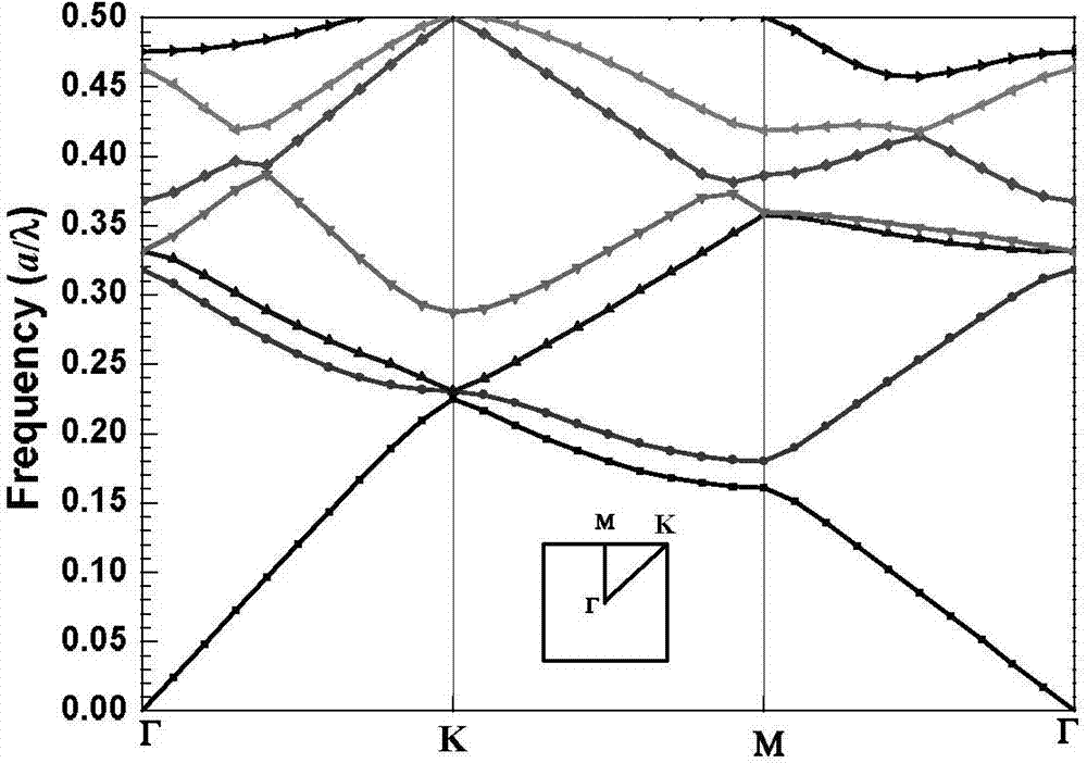
[0035] From figure 2 It can be seen from the shown energy band structure that the photonic crystal plate does not have a full band gap in the TM polarization state.
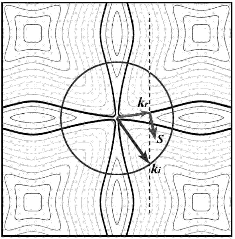
[0036] image 3 The distribution of equifreq...
Embodiment 2
[0046] With embodiment 1, radius r=0.5a cross-sectional shape is the Al of circle 2 o 3 The rods (dielectric constant ε=10) are periodically arranged in the air (n=1) according to the square lattice structure, and the photonic crystal plate is obtained. Cut the photonic crystal plate along the ΓM direction, when the TM polarized electromagnetic wave with a relative frequency of ω=0.335 is 10°inc When the air is incident on the photonic crystal plate at any angle within the incident angle range of <60°, a refracted wave with a refraction angle of 13° can be excited in the photonic crystal plate along the ΓM direction at the incident interface, and its equiphase plane is parallel to the propagation direction, realizing The self-collimated zero-phase-shift transmission of electromagnetic waves in the photonic crystal plate is realized.
Embodiment 3
[0048] Same as in Example 1, the circular air columns are arranged periodically on the Al 2 o 3 In the dielectric background, the radius of the air column is 0.25a, and the filling ratio is 80.4%, resulting in a photonic crystal plate. Cut the photonic crystal plate along the ΓM direction, when the TM polarized electromagnetic wave with a relative frequency of ω=0.3345 is 10°inc When the air is incident on the photonic crystal plate at any angle within the incident angle range of <60°, a refracted wave with a refraction angle of 11.5° can be excited in the photonic crystal plate along the ΓM direction at the incident interface, and its equiphase plane is parallel to the propagation direction, realizing The self-collimated zero-phase-shift transmission of electromagnetic waves in the photonic crystal plate is realized.
[0049] When the radius of the air column is changed or another medium is used as the medium background, the operating frequency (wavelength) of the self-col...
PUM
| Property | Measurement | Unit |
|---|---|---|
| Angle of refraction | aaaaa | aaaaa |
Abstract
Description
Claims
Application Information
 - R&D
- Intellectual Property
- Life Sciences
- Materials
- Tech Scout
- Unparalleled Data Quality
- Higher Quality Content
- 60% Fewer Hallucinations
Browse by: Latest US Patents, China's latest patents, Technical Efficacy Thesaurus, Application Domain, Technology Topic, Popular Technical Reports.
© 2025 PatSnap. All rights reserved.Legal|Privacy policy|Modern Slavery Act Transparency Statement|Sitemap|About US| Contact US: help@patsnap.com


