Suspension display rack

Inactive Publication Date: 2007-01-25
KAO JUI CHIEN
View PDF5 Cites 45 Cited by
  • Summary
  • Abstract
  • Description
  • Claims
  • Application Information

AI Technical Summary

Problems solved by technology

However, with the fixed distance of the adjacent seats, each seat only retain one kind of the screwdriver such that the conventional suspension rack can not hang screwdrivers with different specifications.
Furthermore, the seats are securely mounted on the base and can not be separated from the base such that the quantity of the seats can not be changed and therefore, the conventional suspension display rack is not versatile.

Method used


Image

  • Suspension display rack
  • Suspension display rack
  • Suspension display rack

Examples


Embodiment Construction

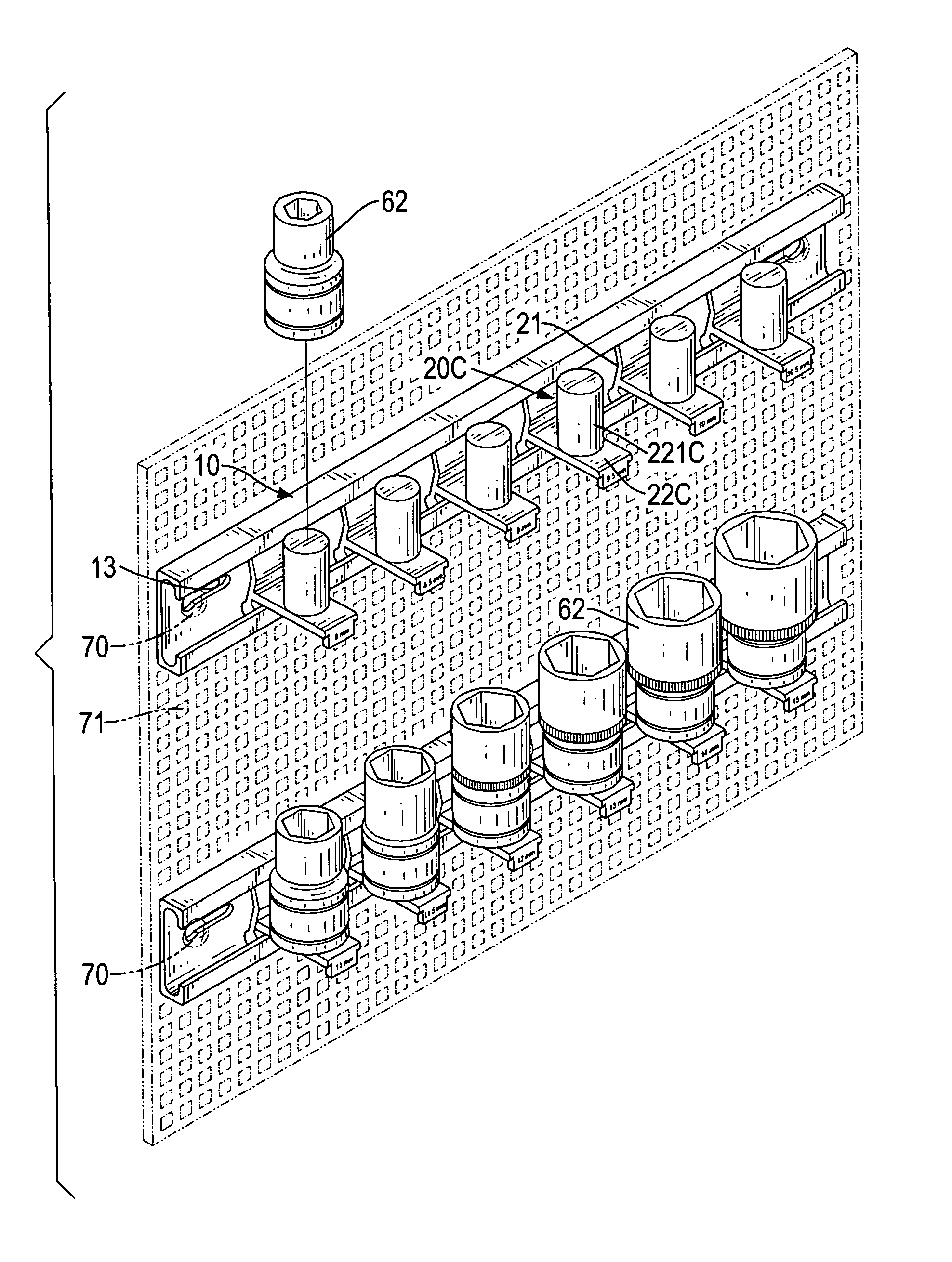
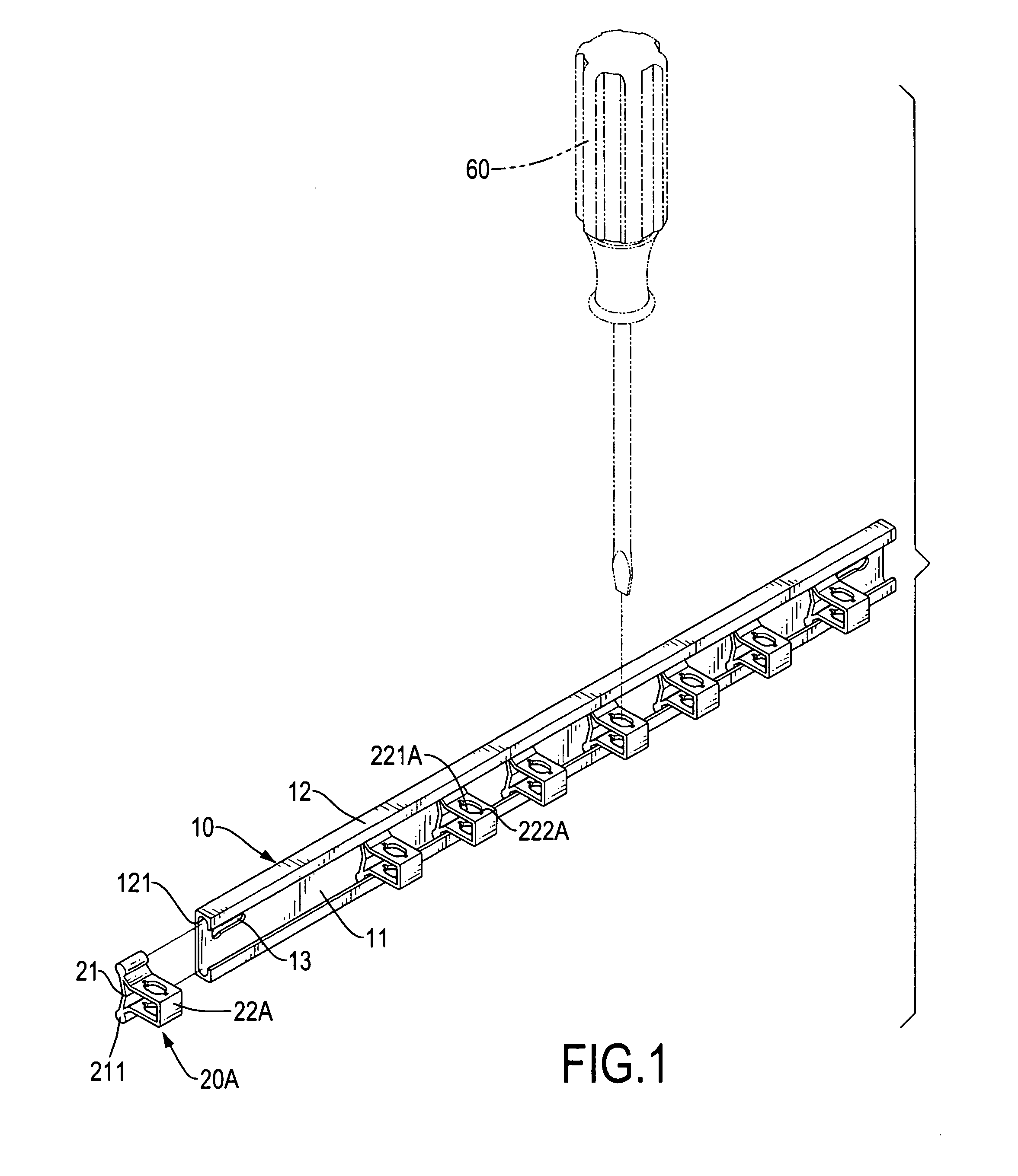
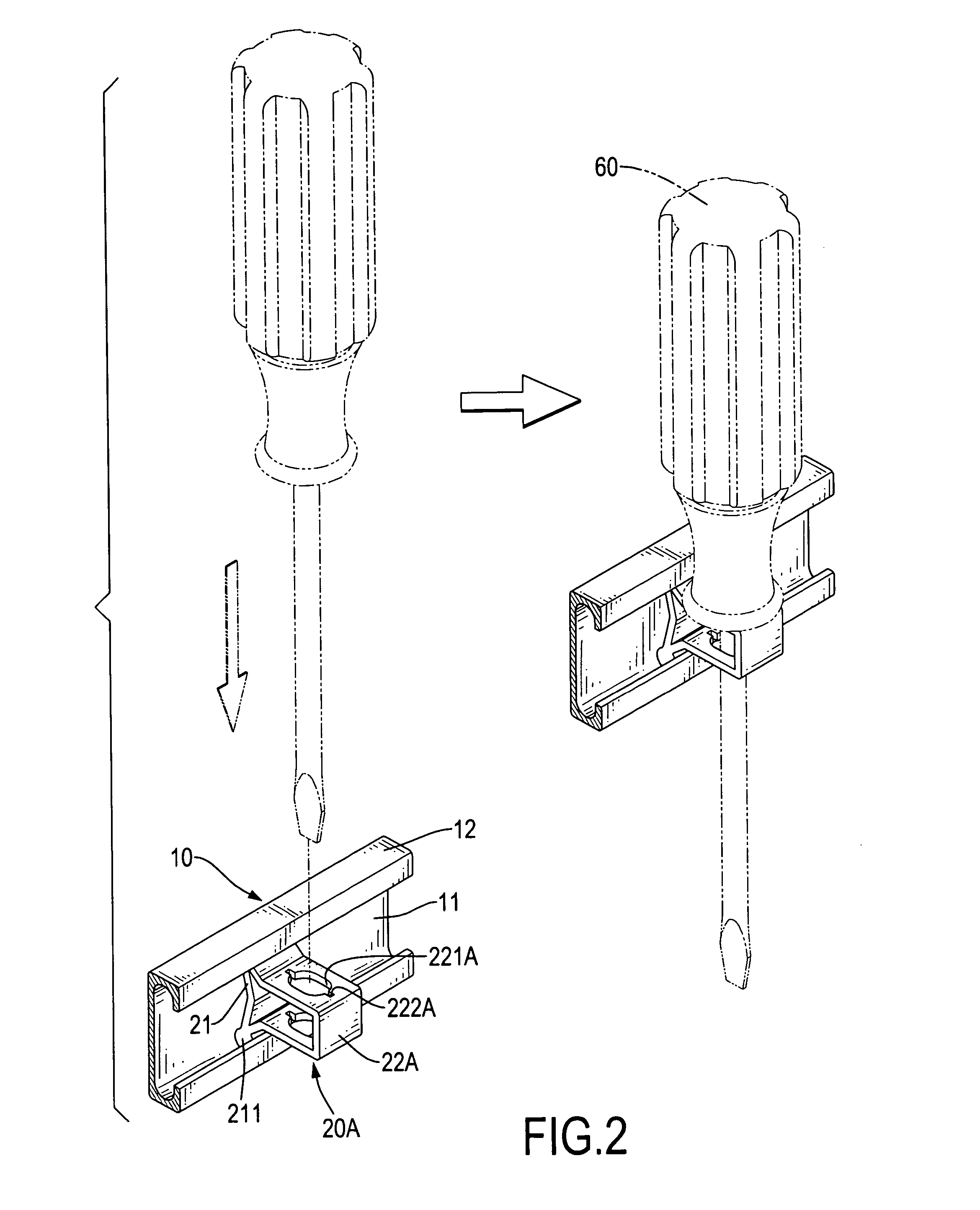
[0023] With reference to FIGS. 1-4, a first preferred embodiment of a suspension display rack for hand tools comprises a rail (10) and multiple sliding blocks (20A).

[0024] The rail (10) is formed as a substantially C-like longitudinal back-strip (11) with two hooks (12) i.e., an upper hook and a lower hook symmetrical with the upper hook formed in a same direction on the back-strip (11). Two arcuate longitudinal grooves (121) are respectively defined at joints where the hooks (12) meet the back-strip (11). Two securing members (13) such as holes are respectively defined in opposed ends of the back-strip (11) whereby the rail (10) can be secured to a surface such as wall via two screws being respectively extended through the securing members (13). In the first preferred embodiment of the present invention, the securing members (13) are two oval holes and two screws can be respectively inserted into the oval holes to fasten the rail (10) to a surface.

[0025] The multiple sliding bloc...


PUM


Abstract

A suspension display rack for tools has a rail and multiple sliding blocks. The rail has a back-strip, two longitudinal hooks joined to the back-strip and two grooves respectively defined at the joins between the hooks and the back-strip. The multiple sliding blocks each have a base, a seat extending from the base, and two bulbous rods formed at the base. The bulbous rods are respectively and matingly received in the grooves, whereby the hand tools can be hung on the sliding blocks which can transversely slide along the rail.

Description

BACKGROUND OF THE INVENTION [0001] 1. Field of the Invention [0002] The present invention relates to a suspension display rack for hand tools, and more particularly to a suspension display rack on which the hand tools can be arranged with a freely arranged distance between the tools. [0003] 2. Description of Related Art [0004] A conventional tool display rack comprises a base, multiple seats respectively mounted on the base to abut or grip blades of screwdrivers, and a board mounted on the base to press against handles of the screwdrivers. Each seat has an abutting means and a handling means thereby cooperating with the board to securely fasten the screwdrivers to the rack. [0005] However, with the fixed distance of the adjacent seats, each seat only retain one kind of the screwdriver such that the conventional suspension rack can not hang screwdrivers with different specifications. Furthermore, the seats are securely mounted on the base and can not be separated from the base such t...

Claims


Application Information

Patent Timeline
IPC IPC(8): A47F5/08
CPCA47F5/0807B25H3/04A47F7/0028
Inventor KAO, JUI-CHIEN
Owner KAO JUI CHIEN
Why Eureka
Try Eureka