Magnetic bearing assembly using repulsive magnetic forces

a magnetic force and bearing technology, applied in the field of magnetic bearings, can solve the problems of axially directed displacement instability, magnetic bearing structure requires a design which may become quite complicated, and friction and wear

Inactive Publication Date: 2007-02-01
ROZMUS JOHN J
View PDF25 Cites 5 Cited by
  • Summary
  • Abstract
  • Description
  • Claims
  • Application Information

AI Technical Summary

Benefits of technology

[0007] According to an embodiment of the present invention, a magnetic bearing assembly has an inner magnetic component and at least one outer magnetic component, each having a magnetic source. The assembly uses repulsive magnetic forces to control relative movement between the inner and outer components in first and second directions while permitting relative movement between the components in a third direction. The inner component and outer components define at least two continuous magnetic gaps, each angled with respect to the axis of the inner component. Each gap provides force vectors in the first and second directions, and the gaps collectively provide a stable equilibrium in the first and second directions. With a stable equilibrium, in response to relative movement of components to cause a decrease in the gap width of one of the gaps in the first or second direction, magnetic repulsive forces at the decreased gap width urge the components away from each other along the first or second directions to return to equilibrium.
[0010] In a further embodiment according to the present invention, the magnetic bearing is a linear magnetic bearing and comprises the inner component, outer components, and housing, as well as a mechanical element for controlling lateral and vertical movement between the inner component and the two outer components. In this embodiment, the gaps are configured such that they all exert a force in the same axial direction, namely opposing gravity. With this configuration, as the load on the load-bearing component increases, the width of the gaps in the axial direction decreases thereby increasing the repulsive magnetic force between the components.

Problems solved by technology

Mechanical bearings necessarily involve mechanical contact between the components, leading to well-known problems associated with friction and wear.
However, magnetic bearing structures require a design which may become quite complicated; for example, for radial magnetic bearings, it is necessary to maintain the rotating component aligned axially with the non-moving component, such as by providing a second magnetic gap to maintain such alignment.
In other words, if such a bearing element is designed to be stable against transverse displacements, it will be unstable against axially directed displacements, and vice versa.

Method used


Image

  • Magnetic bearing assembly using repulsive magnetic forces
  • Magnetic bearing assembly using repulsive magnetic forces
  • Magnetic bearing assembly using repulsive magnetic forces

Examples


Embodiment Construction

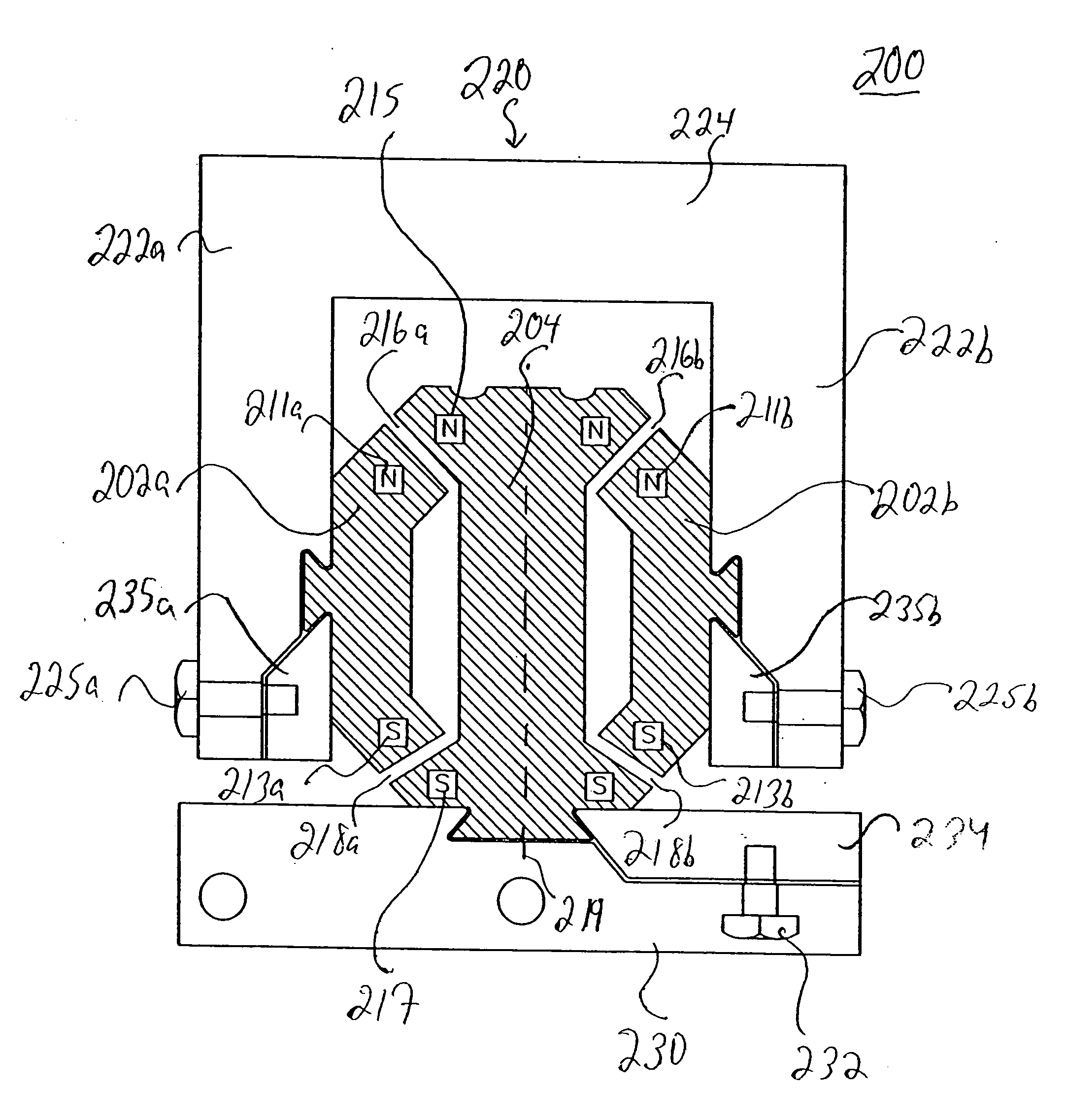
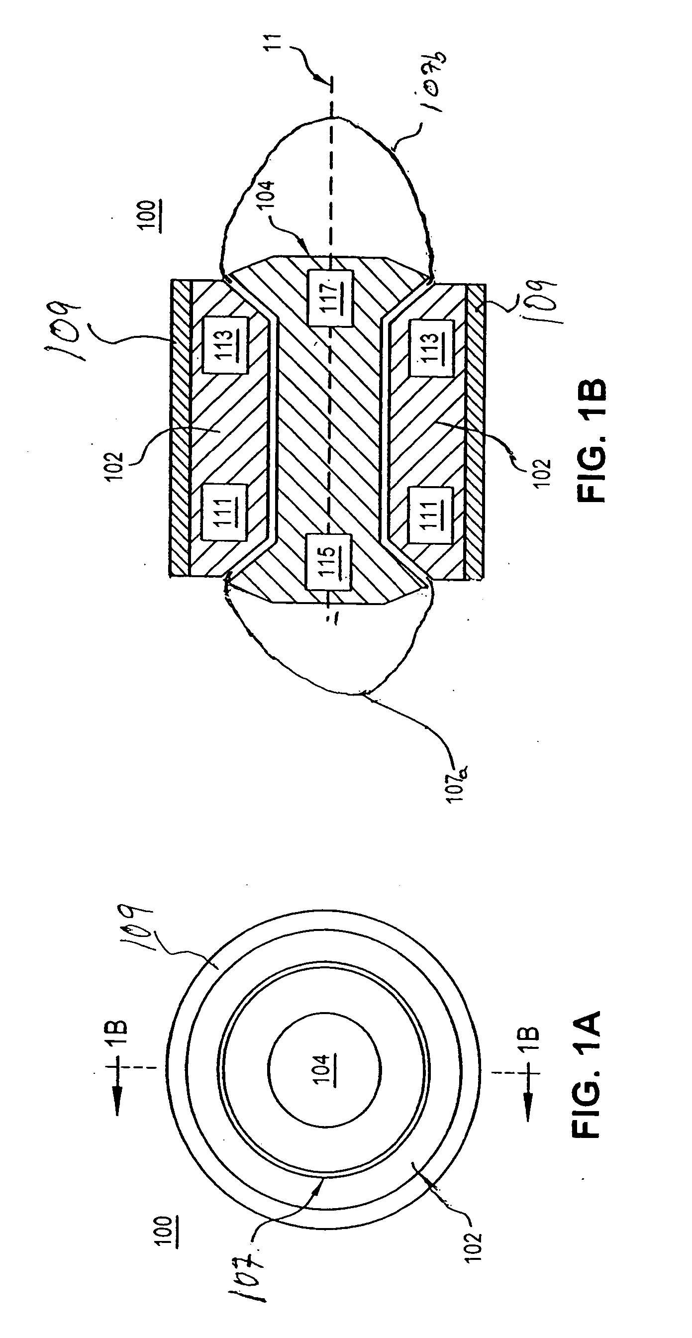
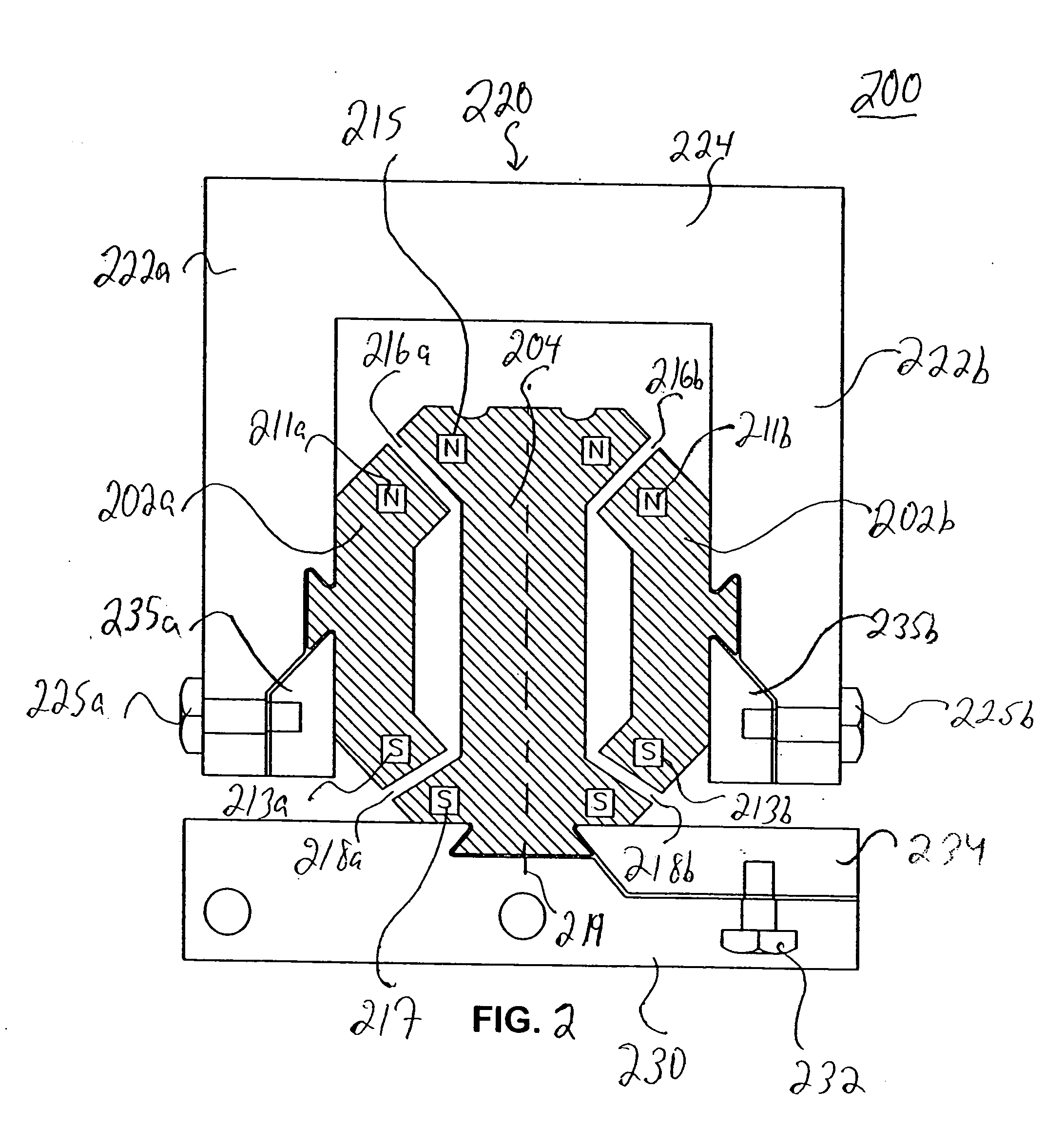
[0017] A general embodiment of the present invention is directed to the utilization of repulsive magnetic forces of components of a magnetic bearing assembly. As referred to herein, the components of the magnetic bearing assembly refer to the magnetic elements of the assembly which comprise a magnetic source. A magnetic bearing may consist only of the two components of the bearing which move relative to one another or it may include the two components and other elements, such as a magnetic shield, a retainer ring, a housing, a base or other known elements of magnetic bearing and related assemblies. The magnetic bearing according to the present invention can be used in a wide variety of industrial applications requiring a stable magnetic bearing, such as in gravity-free environments (e.g., outer space), and in any system under gravity requiring such a bearing.

[0018] According to a general embodiment of the invention, the magnetic bearing assembly has an inner magnetic component and ...


PUM


Abstract

A magnetic bearing assembly utilizes repulsive magnetic forces between components, having magnetic sources, of the bearing at two or more gaps which are angled with respect to an axis of the inner component. Each gap provides force vectors in two directions, while allowing for relative movement of the components in a third direction. The gaps collectively provide a stable equilibrium in the first two directions, meaning that, in response to relative movement of the components in the first or second direction causing a decreased gap width, magnetic repulsive forces at the decreased gap width urge the components away from each other to return to equilibrium. The components of a radial magnetic bearing according to the invention move relative to one another rotationally, and the components of a linear magnetic bearing according to the invention move relative to one another longitudinally.

Description

CROSS REFERENCE TO RELATED APPLICATIONS [0001] This application is a continuation application of U.S. patent application Ser. No. 11 / 027,541, filed Dec. 30, 2004, the entire disclosure of which is expressly incorporated by reference herein.STATEMENT REGARDING FEDERALLY SPONSORED RESEARCH [0002] Not applicable. REFERENCE TO SEQUENCE LISTING [0003] Not Applicable. TECHNICAL FIELD OF THE INVENTION [0004] The present invention relates generally to magnetic bearings and, more particularly, to linear or radial magnetic bearings using repulsive magnetic forces. BACKGROUND OF THE INVENTION [0005] Mechanical bearings necessarily involve mechanical contact between the components, leading to well-known problems associated with friction and wear. Repulsive magnetic forces have been utilized in magnetic bearings, for example, to provide a non-contact, low-friction bearing. However, magnetic bearing structures require a design which may become quite complicated; for example, for radial magnetic b...

Claims


Application Information

Patent Timeline
Patent Type & Authority Applications(United States)
IPC IPC(8): H02K7/09
CPCF16C29/00F16C29/045F16C39/063F16C32/0434F16C32/0425
Inventor ROZMUS, JOHN J.
Owner ROZMUS JOHN J
Why Eureka
Try Eureka