Material forming tool and method for forming a material

Inactive Publication Date: 2007-02-22
BATTELLE ENERGY ALLIANCE LLC
View PDF32 Cites 60 Cited by
  • Summary
  • Abstract
  • Description
  • Claims
  • Application Information

AI Technical Summary

Problems solved by technology

Researchers and designers have faced many challenges with respect to the creation of various new

Method used


Image

  • Material forming tool and method for forming a material
  • Material forming tool and method for forming a material
  • Material forming tool and method for forming a material

Examples


Embodiment Construction

[0022] This disclosure of the invention is submitted in furtherance of the constitutional purposes of the U.S. Patent Laws “to promote the progress of science and useful arts” (Article 1, Section 8).

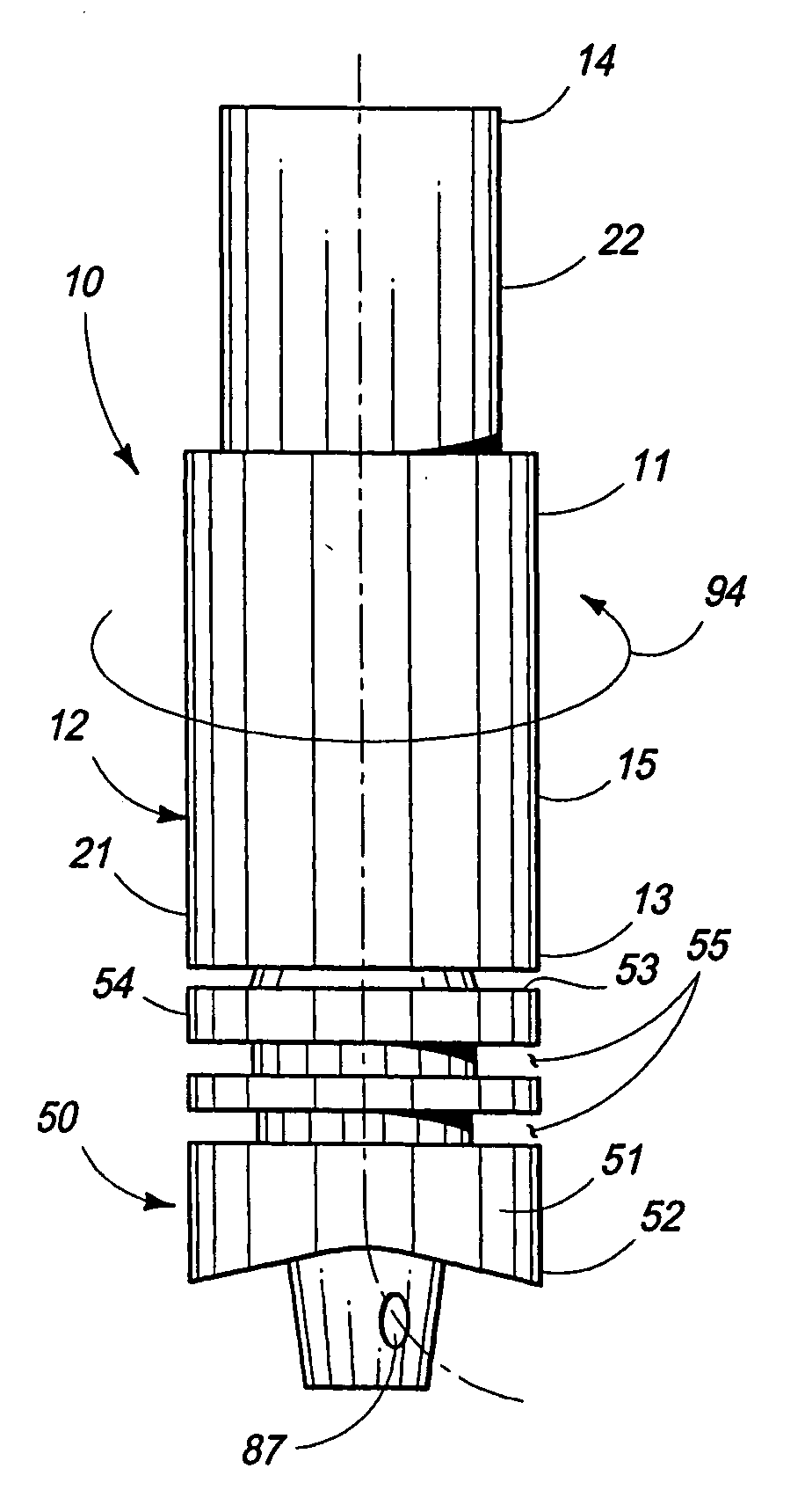
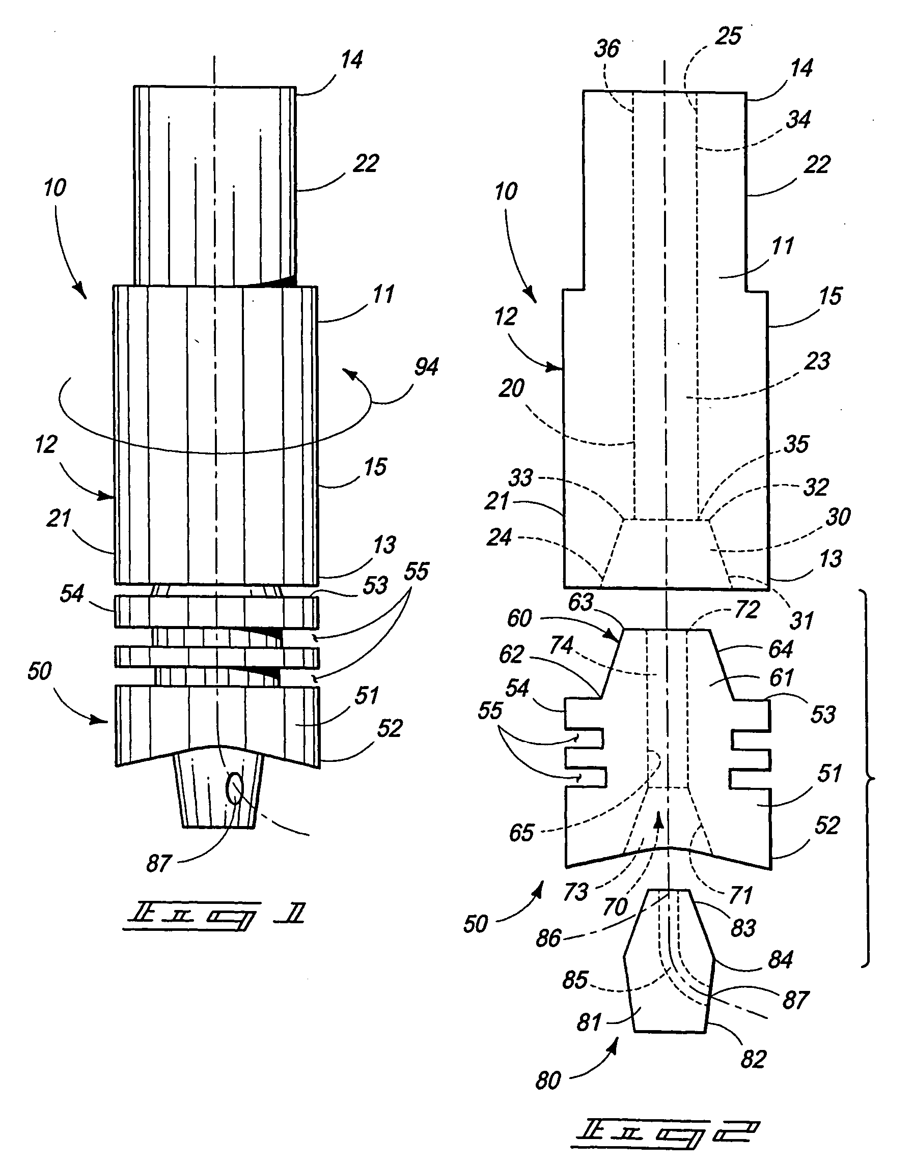
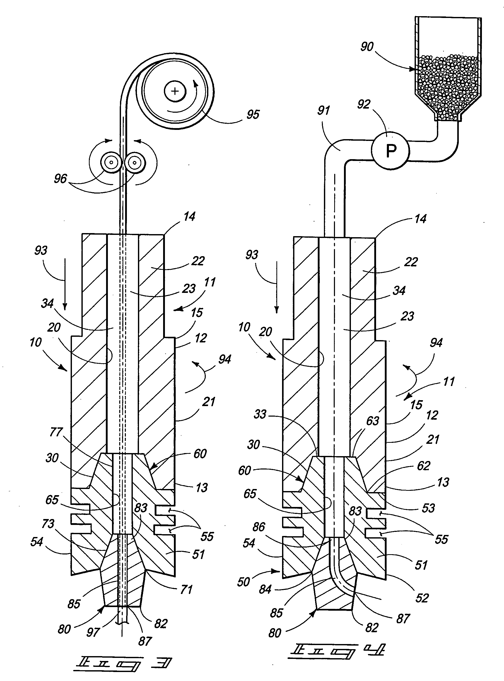
[0023] A material forming tool of the present invention is generally indicated by the numeral 10 in FIG. 1 and following: Referring now to FIGS. 1 and 2, for example, the material forming tool 10 of the present invention is illustrated and which includes a shank portion 11. The shank portion is defined by an elongated main body 12, which has a first end 13, and an opposite second end 14 which is forcibly engaged by a machine (not shown) and which imparts rotational movement to the shank as indicated by the arrows as placed in the various drawings. The main body is defined by an exterior facing surface 15, and an opposite interior facing surface 20 (FIG. 2). As seen in FIGS. 1 and 2, the shank portion, and more specifically the exterior-facing surface 15 may be defined by a first outside...


PUM

PropertyMeasurementUnit
Timeaaaaaaaaaa
Thicknessaaaaaaaaaa
Forceaaaaaaaaaa

Abstract

A material forming tool and a method for forming a material is described and which includes a shank portion; a shoulder portion which releasably engages the shank portion; a pin which releasably engages the shoulder portion, and wherein the pin defines a passageway; and a source of a material coupled in material flowing relation relative to the pin and wherein the material forming tool is utilized in methodology which includes providing a first material; providing a second material, and placing the second material into contact with the first material; and locally plastically deforming the first material with the material forming tool so as mix the first material and second material together to form a resulting material having characteristics different from the respective first and second materials.

Description

GOVERNMENT RIGHTS [0001] The United States Government has certain rights in this invention pursuant to Contract No. DE-AC07-05ID14517 between the United States Department of Energy and Battelle Energy Alliance, LLC.TECHNICAL FIELD [0002] The present invention relates to a material forming tool, and method for forming a material, and more specifically to a friction stir welding tool which has parts which are replaceable, and which is further useful in forming materials which may comprise alloys, composites or the like. BACKGROUND OF THE INVENTION [0003] The prior art is replete with numerous examples of friction stir welding devices which are useful in welding various materials. As a general matter, friction stir welding is a technique whereby a rotating tool is brought into forceable contact with an adjacent work piece to be welded, and the rotation of the tool creates frictional heating of the adjacent work piece, and extensive deformation as mixing occurs along a plastic zone. Upo...

Claims


Application Information

Patent Timeline
IPC IPC(8): B23K20/12
CPCB23K20/122B23K20/128B23K20/1275
Inventor CHARLES R., TOLLEDENIS E., CLARKHERSCHEL B., SMARTTKAREN S., MILLER
Owner BATTELLE ENERGY ALLIANCE LLC
Why Eureka
Try Eureka