Secure adjustable strike plate

a technology of adjustable strike plate and lock plate, which is applied in the direction of building locks, constructions, fastening means, etc., can solve the problems of building settle or change, door will not close, and serious security risks

Inactive Publication Date: 2007-02-22
ADJUSTABLE STRIKE DEFENSE
View PDF14 Cites 15 Cited by
  • Summary
  • Abstract
  • Description
  • Claims
  • Application Information

AI Technical Summary

Benefits of technology

[0019] A strike plate assembly according to the present invention, is for mounting on a door frame. The door frame forms a clearance hole for receiving the strike plate assembly. A mounting plate is affixed to the door frame in the clearance hole. The mounting plate forms an opening for receiving a bolt from a door knob or lock, such as a dead bolt lock, and forms two substantially parallel slots. A strike plate is affixed to the mounting plate. The strike plate also forms an opening for receiving a bolt from a door knob or lock and forms two substantially parallel slots which are at right angles to the two substantially parallel slots of the mounting plate. Each of the parallel slots of strike plate crosses over a corresponding one of the parallel slots of the mounting plate when the strike plate is properly affixed to the mounting plate. A pair of nuts and bolts affix the strike plate to the mounting plate. One bolt fits through each of the parallel slots of the strike plate and the corresponding parallel slot of the mounting plate. The pair of nuts secure the pair of bolts such that the position of the bolts can be adjusted in the parallel slots of the mounting plate and in the parallel slots of the strike plate, allowing the strike plate to be adjusted both vertically and horizontally with respect to the mounting plate.

Problems solved by technology

If either the strike or the lock are out of position and do not mate correctly, the door will not close properly creating a serious security risk.
The problem with accurately positioning the lock and strike is twofold: First, there is the problem involved in the original mounting of the lock and the strike.
The second problem arises when a building settles or changes relative position as a consequence of age or other factors.
In those circumstances, it is typical that a door and door jamb will become out of alignment with one another so that the lock does not mate properly with the strike.
This creates a serious problem not only with regard to security and the aesthetic look of the door; but, as one attempts to reposition the strike by reboring holes into the door jamb, it weakens the structure of the door jamb and creates additional security and aesthetic problems.
The disadvantages of this device is that it is complicated to manufacture and assemble and requires spring loaded parts which are subject to fatigue and therefore, pose serious security risks.
It does not permit mounting both a latch and a deadbolt.
A significant disadvantage of the Allenbaugh device is that the vertical adjustment is minor and requires the reboring of the mounting socket in the door jamb.
A second problem with the Allenbaugh device is that it is not suitable for mounting both a latch and a deadbolt without reboring the door jamb.
As mentioned before, this is both aesthetically displeasing and poses a security risk.
Wartain's device cannot be vertically adjusted without reboring the door jamb.
The Bahorik device does not provide for the universal mounting of either a latch or a deadbolt and is severely limited with respect to vertical adjustment in that it is not continuously adjustable.
The disadvantage is that the springs will fatigue over time and it provides only limited vertical and lateral adjustment.
A further disadvantage of the Flora device is that it requires that both the latch and deadbolt strikes be included in a single part.
U.S. Pat. No. 1,733,412 to Karns for Adjustable Striker Plate discloses an adjustable striker that is adjustable only in the horizontal direction and therefore has the disadvantage that it cannot be adjusted vertically without reboring the door jamb creating both the aesthetic and security problems that have been previously mentioned.

Method used


Image

  • Secure adjustable strike plate
  • Secure adjustable strike plate
  • Secure adjustable strike plate

Examples


Embodiment Construction

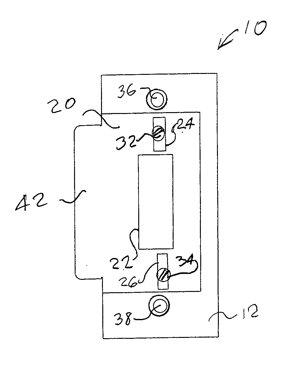
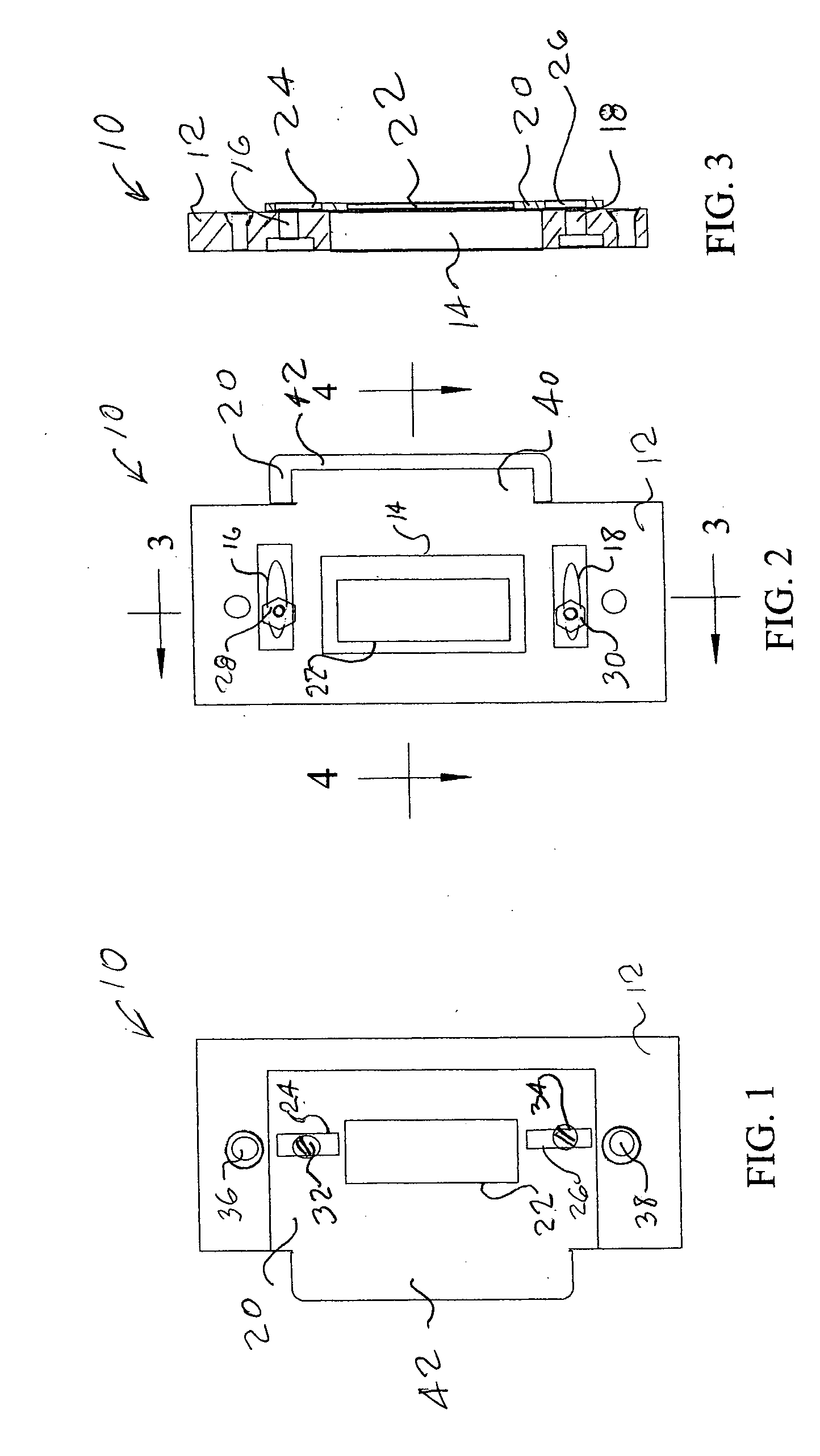
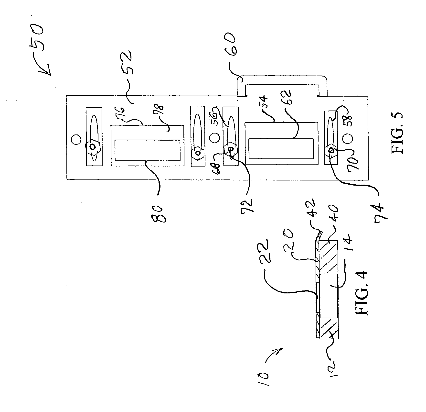
[0029] Referring now to the drawing, and in particular to FIGS. 1-4, a strike plate assembly according to the present invention is referred to generally by reference numeral10. Strike plate assembly 10 is for mounting on a door frame, not shown. The door frame forms a clearance hole for receiving the strike plate assembly. A mounting plate 12 is affixed to the door frame in the clearance hole. Mounting plate 12 forms an opening 14 for receiving a bolt from a door knob or lock, such as a dead bolt lock. Mounting plate 12 also forms two substantially parallel slots, first horizontal slot 16 and second horizontal slot 18. A strike plate 20 is affixed to the mounting plate. Strike plate 20 also forms an opening 22 for receiving a bolt from a door knob or lock and forms two substantially parallel slots, first vertical slot 24 and second vertical slot 26. The substantially parallel slots in strike plate 20 are at right angles to the two substantially parallel slots of mounting plate 12. E...


PUM


Abstract

A strike plate assembly for mounting on a door frame is disclosed. The door frame forms a clearance hole for receiving the strike plate assembly. A mounting plate is affixed to the door frame in the clearance hole. The mounting plate forms an opening for receiving a bolt from a door knob or lock, such as a dead bolt lock, and forms two substantially parallel slots. A strike plate is affixed to the mounting plate. The strike plate also forms an opening for receiving a bolt from a door knob or lock and forms two substantially parallel slots which are at right angles to the two substantially parallel slots of the mounting plate. Each of the parallel slots of strike plate crosses over a corresponding one of the parallel slots of the mounting plate when the strike plate is properly affixed to the mounting plate. A pair of nuts and bolts affix the strike plate to the mounting plate. One bolt fits through each of the parallel slots of the strike plate and the corresponding parallel slot of the mounting plate. The pair of nuts secure the pair of bolts such that the position of the bolts can be adjusted in the parallel slots of the mounting plate and in the parallel slots of the strike plate, allowing the strike plate to be adjusted both vertically and horizontally with respect to the mounting plate. The opening formed by the strike plate substantially overlaps the opening formed by the mounting plate, although the opening formed by the mounting plate would normally be substantially larger than the opening formed by the strike plate.

Description

CROSS-REFERENCE TO RELATED APPLICATIONS STATEMENT REGARDING FEDERALLY SPONSORED RESEARCH OR DEVELOPMENT [0001] Not Applicable INCORPORATION-BY-REFERENCE OF MATERIAL SUBMITTED ON A COMPACT DISC [0002] Not Applicable BACKGROUND OF THE INVENTION [0003] 1. Field of the Invention [0004] The present invention relates to strike plates for latch bolts, dead bolts and other bolts associated with door knobs and locks, and in one of its aspects to strike plates and strike plate assemblies which can be adjusted to match the position of the bolt or bolts when the door is closed. [0005] 2. Description of Related Art [0006] Conventional door hardware includes a door knob or lock, with a bolt and a cooperating strike mounted on the door jamb to receive the bolt. In the most common arrangement, the strike plate is a simple stamped metal plate which forms an opening of suitable size and shape to receive the bolt with some clearance. In a typical arrangement, the strike is mounted to the door jamb usi...

Claims


Application Information

Patent Timeline
Patent Type & Authority Applications(United States)
IPC IPC(8): E05B15/02
CPCE05B15/0245E05B2015/0275Y10T292/705
Inventor NICHOLAS, MARVIN R. JR.STEVENS, DAVID L.
Owner ADJUSTABLE STRIKE DEFENSE
Why Eureka
Try Eureka