
Flute attachment

a technology for flutes and strings, applied in the field of flute attachments, can solve the problems of b>100/b> not being able to effectively support the weight of the flute, and the sectional rotation problem,

Inactive Publication Date: 2007-03-01
LEE HO FAN
View PDF10 Cites 9 Cited by
  • Summary
  • Abstract
  • Description
  • Claims
  • Application Information

AI Technical Summary

Benefits of technology

[0011] Therefore, the object of the present invention is to provide a flute attachment that can solve the aforesaid horizontal rotation and sectional rotation problems commonly encountered in the prior art besides supporting partial weight of a flute.
[0012] Accordingly, a flute attachment of the present invention is adapted for use on a flute having a round tubular flute body extending along a flute axis and having upper and lower surfaces opposite to each other in a first direction transverse to the flute axis, and front and rear surfaces opposite to each other in a second direction transverse to the first direction. The flute body includes a head joint having a mouthpiece, a foot joint, a body joint between the head and foot joints, and a plurality of rods and keys which are disposed such that in a play position, as a result of weights of the rods and keys, an urging force is generated to rotate the upper surface about the flute axis towards a flute player. The flute attachment includes a securing member and a resisting member. The securing member is formed from a flexible material, and is adapted to be attached fittingly to the lower surface of the flute body for a thumb of the flute player to normally rest thereagainst to thereby balance and support the flute. The securing member includes a base segment which is disposed beneath the lower surface, and which extends angularly about the flute axis to form front and rear pad regions that terminate respectively at front and rear lateral edges which are opposite to each other in the second direction. The front lateral edge is configured to be in frictional engagement with the front surface. The resisting member includes a fulcrum region joined with the rear lateral edge, a weight end extending from the fulcrum region towards the rear surface, and a tab end which extends from the fulcrum region and away from the flute axis, and which, in cooperation with the rear pad region, defines a thumb abutting area such that, as a result of resting of the thumb of the flute player against the rear pad region, a primary thumb force, which is directed towards the flute axis, is generated to partly counteract a tendency of the flute to displace downwardly due to application of forces on the keys by the other fingers of the flute player and partial weight of a flute and to partly prevent undesirable deviation of the foot joint toward the flute player due to application of pressure to the mouthpiece, while a secondary thumb force acts on the tab end to bring the weight end to abut against the rear surface so as to guard against rotation of the body joint about the flute axis toward the flute player.

Problems solved by technology

In addition, since the keys 11, plates, and rods of the flute 1 are provided on upper and rear portions of the tubular wall of the flute 1, the entire flute 1 is liable to rotate about its axis toward the flute player 102, as indicated by the arrow (S) in FIGS. 1 and 2, thereby resulting in the so-called sectional rotation problem.
Moreover, the right thumb 100 cannot help support the weight of the flute 1 effectively.
However, as the little finger needs to operate one of the keys 11 while cooperating with the right thumb 100 to hold the flute 1, the little finger will be somewhat crippled in operating the key 11.
Besides, during shifting of the little finger over the keys 11, shaking of the flute 1 may result due to non-uniform force distribution, thereby affecting the performance of the flute player 102.

Method used


Image

  • Flute attachment
  • Flute attachment
  • Flute attachment

Examples


Embodiment Construction

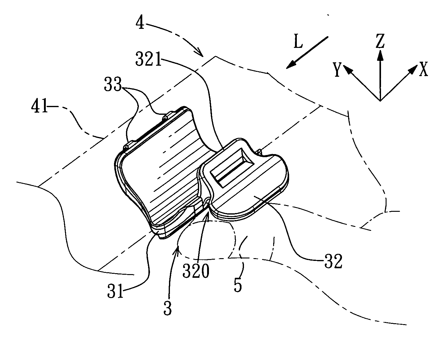
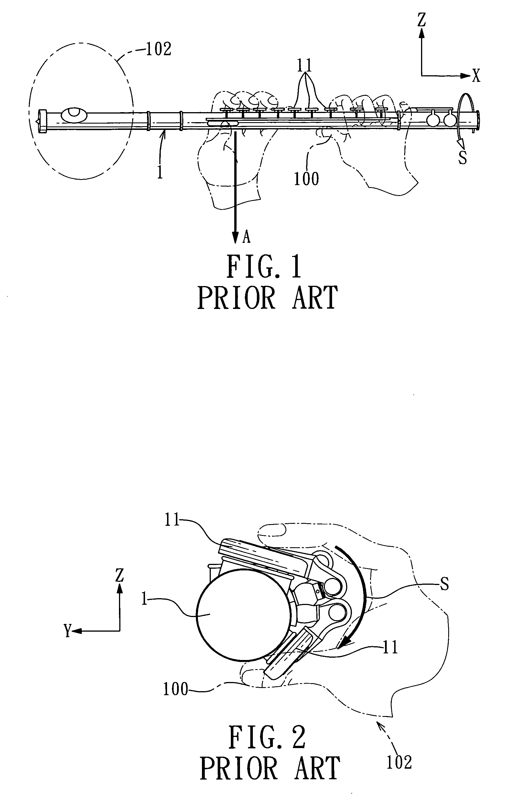
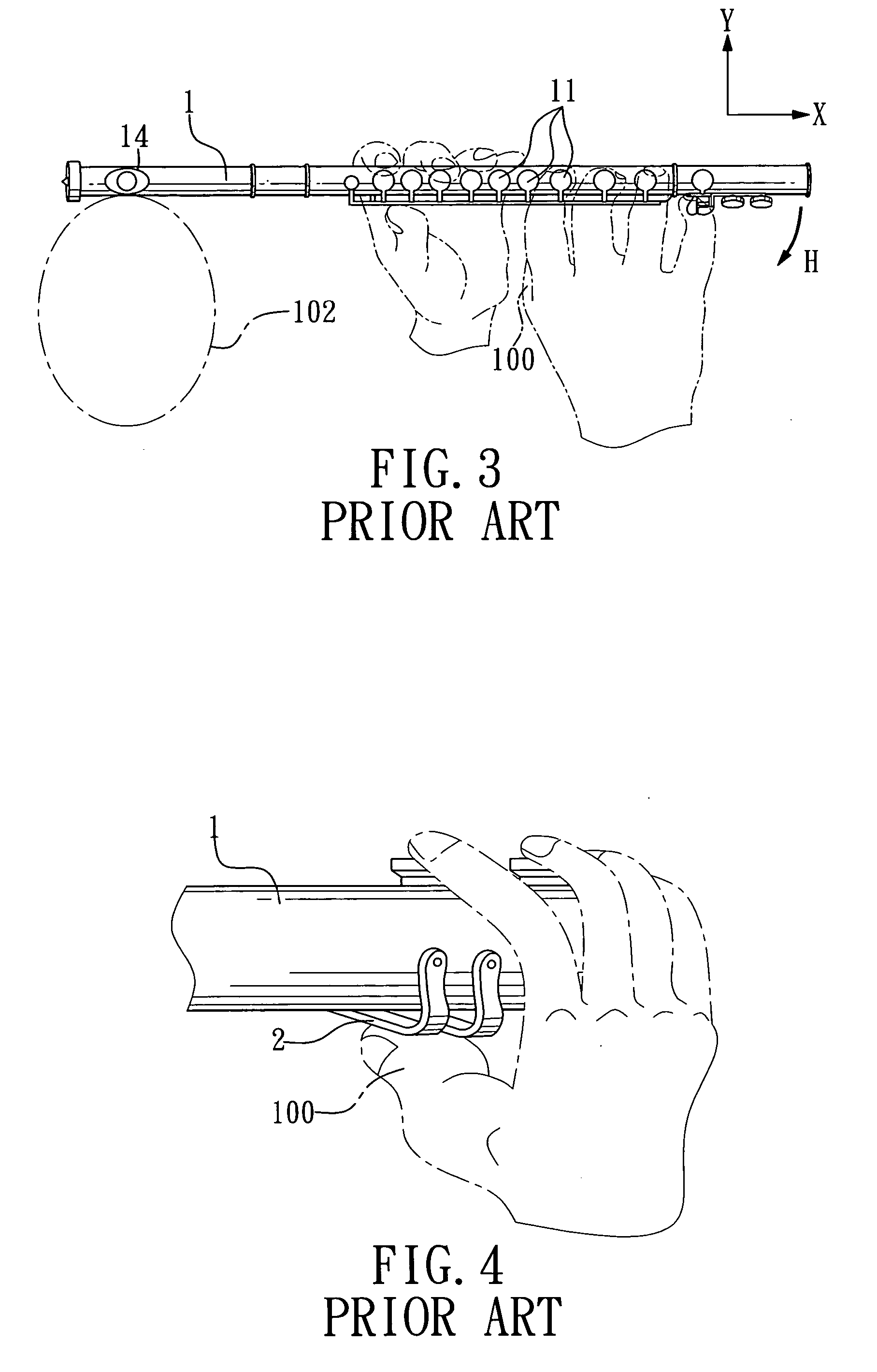
[0023] Referring to FIG. 6, the preferred embodiment of a flute attachment 3 according to the present invention is shown to be attached to a flute 4 having a round tubular flute body 41 extending along a flute axis (L) and having upper and lower surfaces opposite to each other in a first direction transverse to the flute axis (L), and front and rear surfaces opposite to each other in a second direction transverse to the first direction. The flute body 41 includes a head joint 45 having a mouthpiece 451, a foot joint 47, a body joint 46 between the head and foot joints 45, 47, and a plurality of rods and keys 43 which are disposed such that in a play position, as a result of weights of the rods and keys 43, an urging force is generated to rotate the upper surface about the flute axis (L) toward a flute player 502 (see FIG. 8), which results in the so-called sectional rotation problem.

[0024] Referring further to FIGS. 7 and 8, the flute attachment 3 includes a securing member 31 and ...


PUM


Abstract

A flute attachment includes a flexible securing member and a resisting member. The securing member is attached to a lower flute surface for resting of a thumb of the flute player, and has a base segment defining a rear pad region and having a front lateral edge in frictional engagement with a front flute surface. The resisting member includes a fulcrum region joined with a rear lateral edge of the base segment, a weight end extending outward from the fulcrum region, and a tab end extending from the fulcrum region and away from the flute axis. The tab end and the rear pad region define a thumb abutting area for application of forces to prevent undesirable rotation of the flute about the flute axis and to prevent undesirable downward displacement and deviation of the flute during playing.

Description

CROSS-REFERENCE TO RELATED APPLICATION [0001] This application claims priority of Taiwanese Application No. 094213789, filed on Aug. 11, 2005. BACKGROUND OF THE INVENTION [0002] 1. Field of the Invention [0003] The invention relates to a flute attachment, more particularly to a flute attachment which is adapted for resting of a right thumb of a flute player thereon to guard against undesirable rotation of the flute, as well as to support and balance the flute. [0004] 2. Description of the Related Art [0005]FIGS. 1 and 2 show schematically a conventional flute 1, in which, as well as in the rest of the accompanying drawings, the arrow (X) represents a left-to-right direction, the arrow (Z) indicates a top-to-bottom direction, and the arrow (Y) indicates a front-to-rear direction. The flute 1 has a plurality of keys 11 provided on a round tubular wall thereof along an axial direction. In general, a flute player 102 uses all the five fingers of the left hand to operate the keys 11, wit...

Claims


Application Information

Patent Timeline
IPC IPC(8): G10D7/02G10D7/026G10D9/00
CPCG10D7/026G10D9/00
Inventor LEE, HO-FAN
Owner LEE HO FAN
Learn More