
Knitting method of tubular knitted fabric with projection, and tubular knitted fabric with projection

a knitting fabric and projection technology, applied in knitting, textiles and papermaking, medical science, etc., can solve the problems of high production cost and difficult to provide a high supporting performance of such a knitted fabric, and achieve the effect of reducing the need for sewing process, reducing production cost, and improving massage

Inactive Publication Date: 2007-03-08
SHIMA SEIKI MFG LTD
View PDF7 Cites 9 Cited by
  • Summary
  • Abstract
  • Description
  • Claims
  • Application Information

AI Technical Summary

Benefits of technology

[0015] The knitting method of a tubular knitted fabric of the present invention can knit a knitted fabric which requires stretch and a supporting performance, such as e.g. a supporter, in the form of a seamless tubular body by using a flat knitting machine. Further, it can allow the projection part to be formed at an arbitrary location on a knitted fabric surface of the tubular body. Hence, when one puts on such a tubular knitted fabric, the tubular knitted fabric having the projection part can provide an improved massage effect, anti-slip effect, and impact absorbing effect for one's body. Also, since the knitted fabric is knitted in the form of a seamless tubular body, the need for a sewing process can be eliminated. In addition to this, since the projection part is knitted in parallel with the tubular body, the need for the process that the projection part to provide the effects mentioned above is previously formed as a separate part and the projection part is attached to the knitted fabric by sewing or patching can be eliminated to provide laborsaving. Also, since the tubular body is designed as the rib knitting structure and also an elastic yarn is inserted in that tubular body by the inlay, the tubular body can obtain required stretch and supporting performances. Additionally, since only the projection part forming area is knitted by the flechage knitting, the knitting can be carried out with efficiency as a whole. Further, since the knitting of the tubular base knitted fabric and the knitting of the projection part are carried out by the independent processes, respectively, the knitting of the projection part can be carried out with a high design freedom.
[0016] When not only the tubular body of the rib knitting structure but also the projection part are knitted using the elastic yarn, the tubular body having the projection part can be produced with further improved stretch and supporting performances.
[0017] Also, the projection part can be formed with efficiency by the flechage knitting and can be formed in an arbitrary shape and at an arbitrary location on the tubular knitted fabric.
[0018] Further, when the knitted fabric, such as a heel supporter and a knee supporter, is designed to have a fitting portion corresponding in shape to the heel or the knee, the tubular body comes to have courses different in number of stitches. However, according to the present invention, the projections can be arranged in even such a location.

Problems solved by technology

However, since any of the knitted fabrics mentioned above includes the plain knitted fabric part as the base knitted fabric part, even when the elastic yarn is weaved in the plain knitted fabric part by the inlay, it is hard for such a knitted fabric to provide a high supporting performance.
Also, the knitting method wherein the projection part is separately formed and then is attached in the knitted fabric by sewing or patching at a later stage requires complicated works at the later stage and thus high production costs.

Method used

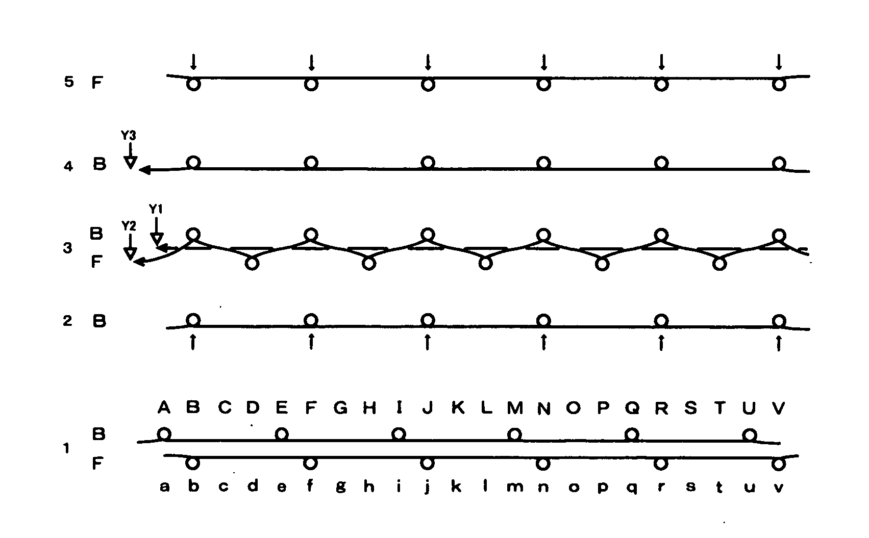

Image

  • Knitting method of tubular knitted fabric with projection, and tubular knitted fabric with projection
  • Knitting method of tubular knitted fabric with projection, and tubular knitted fabric with projection
  • Knitting method of tubular knitted fabric with projection, and tubular knitted fabric with projection

Examples


Embodiment Construction

[0019] Next, a preferred embodiment of the present invention will be described with reference to the accompanying drawings.

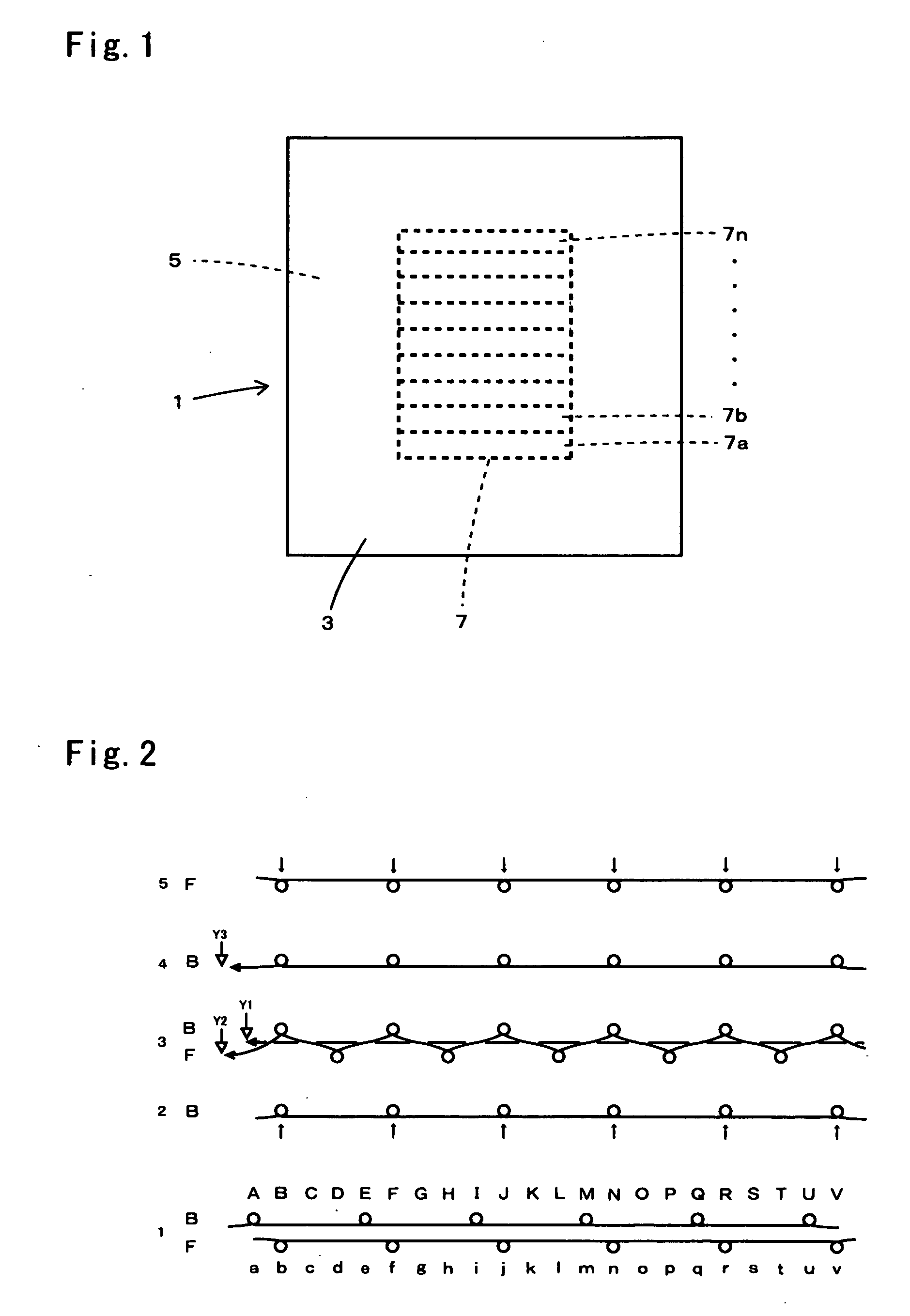
[0020]FIG. 1 is a plan view of a supporter 1 knitted in this embodiment. A front knitted fabric part 3 of a tubular knitted fabric has a projection part 7 at the inside thereof. The tubular knitted fabric part has a two-color rib jacquard structure in which an elastic yarn is inserted by the inlay. In this embodiment, a group of rows of projections is referred to as the projection part.

[0021] While a knitting method using a two-bed knitting machine is described in this embodiment, the knitting can also be carried out using a four-bed knitting machine comprising an upper front needle bed, a lower front needle bed, an upper back needle bed, and a lower back needle bed.

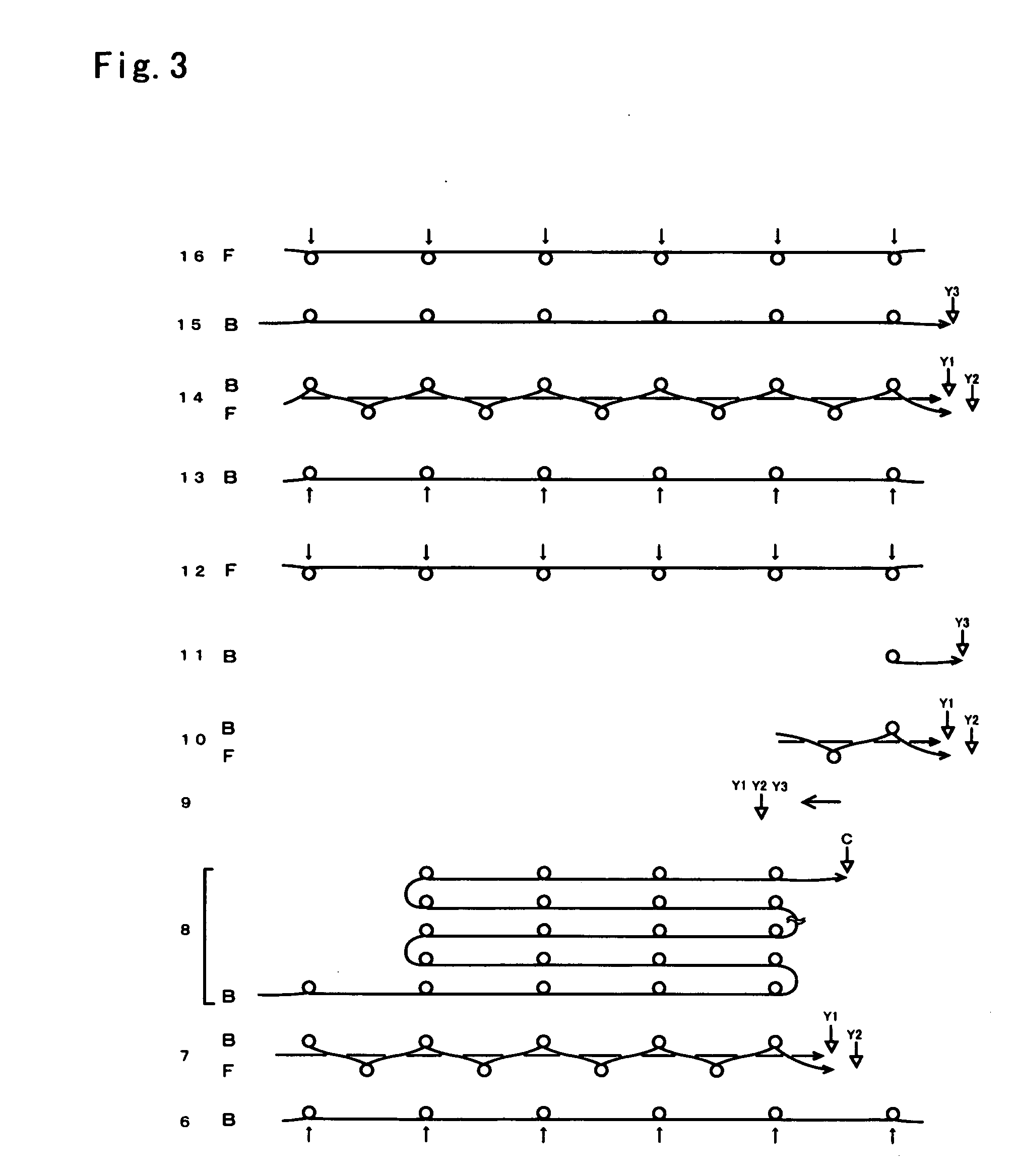
[0022]FIG. 2 shows a knitting process of a base knitted fabric of FIG. 1, and FIG. 3 shows a knitting process of rows of projections of FIG. 1. For convenience and simplification of explanation, o...


PUM

PropertyMeasurementUnit
widthaaaaaaaaaa
elasticaaaaaaaaaa
shapeaaaaaaaaaa

Abstract

The present invention provides a knitting method of a tubular knitted fabric with a projection part having stretch and a supporting performance and formed in an arbitrary shape and at an arbitrary location by using a flat knitting machine. The method comprises the step 1 of knitting a knitted fabric in a tubular form joined at both ends of a knitting width by a rib knitting, while inserting an elastic yarn in the tubular body by an inlay, and the step 2 of knitting only a part for the projection part to be formed on at least either of a front side of the tubular knitted fabric and a back side of the same by a flechage knitting, the step 1 and the step 2 being repeatedly carried out.

Description

TECHNICAL FIELD [0001] The present invention relates to a knitting method of a tubular knitted fabric with projections, such as a sock, a supporter, and the like, using a flat knitting machine, and to a tubular knitted fabric knitted by the same knitting method. BACKGROUND ART [0002] Elastic underwear having stretch and having a capability of providing a massage effect on a human body is known (Patent Document 1). In this elastic underwear, a plain knitted fabric part is knitted as a base knitted fabric part and an elastic yarn is weaved in it by the inlay. In the base knitted fabric part, a so-called float knitted fabric part is mixed wherein wales are produced by putting knitting needles in an operative mode to successively form loops in the wales and wales of various sizes are produced by putting the knitting needles in an inoperative mode for a predetermined course, not to form loops of the wales for the predetermined course. When one puts on this elastic underwear, vertical col...

Claims


Application Information

Patent Timeline
Patent Type & Authority Applications(United States)
IPC IPC(8): D04B7/04D04B1/18D04B1/00D04B1/24D04B1/26
CPCD04B1/18D04B1/26D04B1/24D04B1/108D10B2403/0113D10B2403/0123D10B2403/0231D10B2509/028
Inventor OKUNO, MASAO
Owner SHIMA SEIKI MFG LTD
Learn More