Electroluminescent wire light source on a baseball cap

a technology of electric wire light source and baseball cap, which is applied in the direction of headwear caps, hats, lighting support devices, etc., can solve the problems of small incandescent light source that does not generate significant illumination, incandescent light source generates a significant amount of heat, and incandescent light source and its battery power source are heavy

Inactive Publication Date: 2007-03-22
MIRACLEBEAM PRODS
View PDF10 Cites 48 Cited by
  • Summary
  • Abstract
  • Description
  • Claims
  • Application Information

AI Technical Summary

Benefits of technology

[0025] The power supply and control circuit has a DC power source such as a battery, a DC / AC inverter for converting the direct current from the battery to an alternating current, an on / off switch to turn the electroluminescent wire light source on and off and a control circuit to control the timing and patterns of the light emitted by the electroluminescent wire light source.
[0026] The electroluminescent wire light source is mounted on the exterior surface of the baseball cap on the crown or on the bill. The power supply and control circuit is mounted on the interior surface of the baseball cap between the crown and a hat band or on the crown. Wires connect electroluminescent wire light source and the power supply and control circuit.

Problems solved by technology

However, incandescent light sources generate a significant amount of heat.
Incandescent light sources and their battery power sources are heavy.
Small incandescent light sources do not generate significant illumination.
Small batteries also do not generate significant illumination for incandescent light sources, are depleted quickly and must be replaced often.
Incandescent light sources are bulky and fragile.
They are not shock proof, nor waterproof.
Incandescent light sources tend to have a limited angle of illumination.
Incandescent light sources cannot provide a continuous line of light, but only intermittent points at spaced intervals along a line.
The incandescent light sources are not small enough and flexible enough to provide an illuminated design on a baseball cap.
Unfortunately, optical fibers require an intense, powerful light source.
Optical fiber light sources and their battery power sources are heavy.
Small lightweight optical fiber light sources do not generate significant illumination.
Small lightweight batteries also do not generate significant illumination for optical fiber light sources, are depleted quickly and must be replaced often.
The battery power sources for an optical fiber light source are also bulky.

Method used


Image

  • Electroluminescent wire light source on a baseball cap
  • Electroluminescent wire light source on a baseball cap
  • Electroluminescent wire light source on a baseball cap

Examples


Embodiment Construction

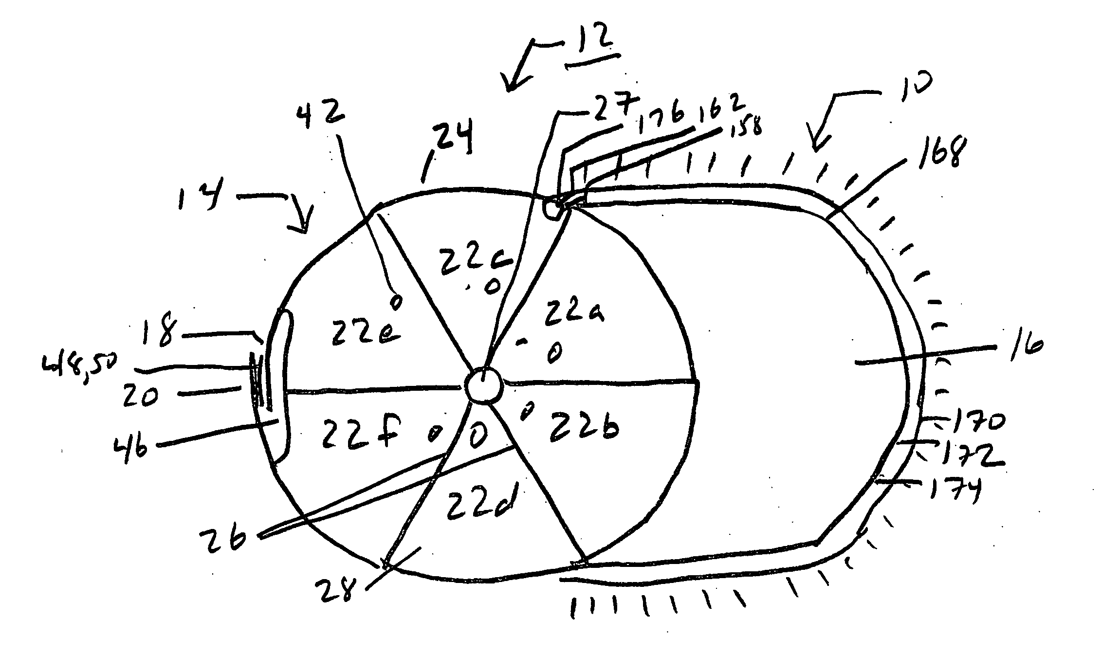
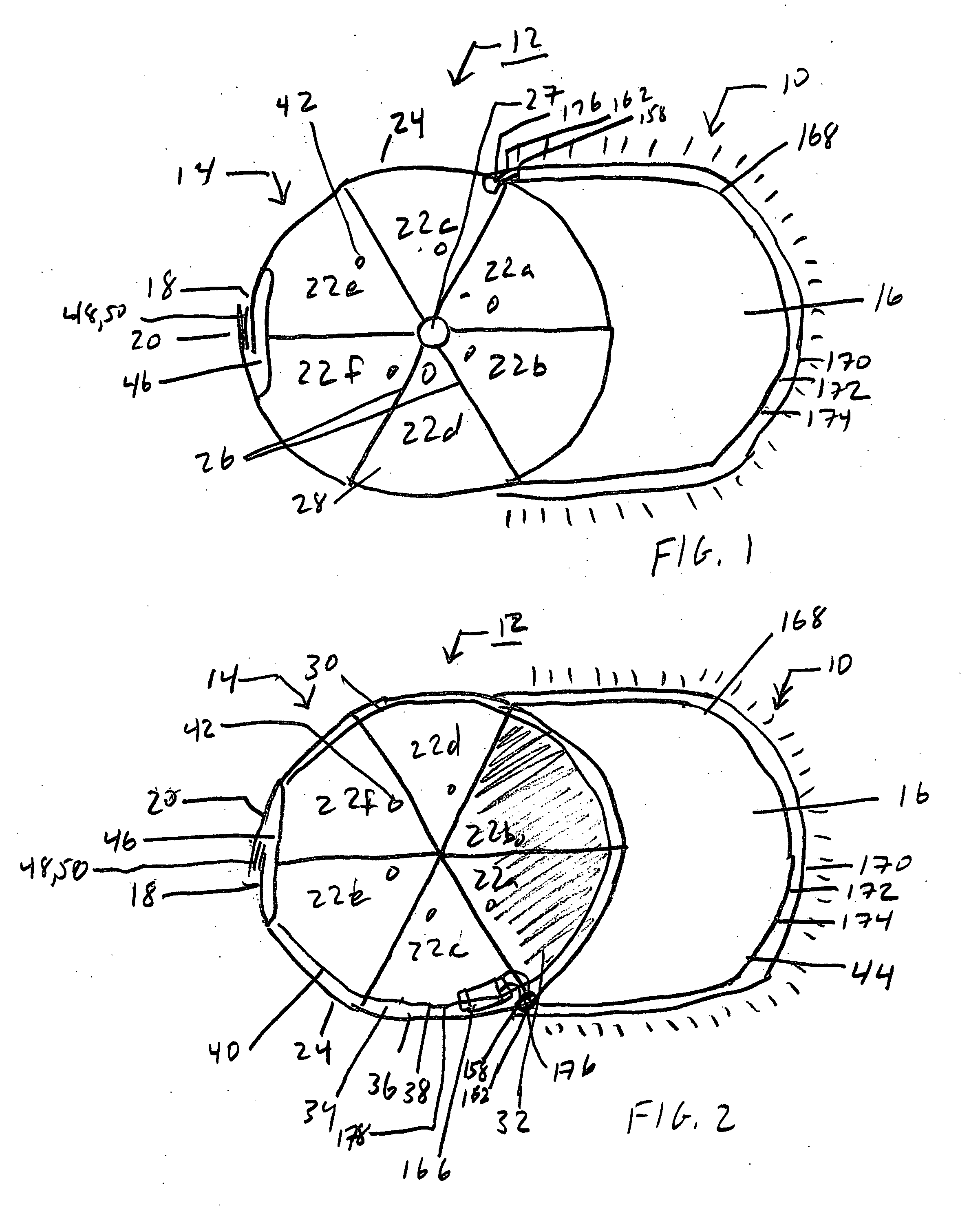
[0043] Reference is now made to FIGS. 1 and 2 illustrating an electroluminescent wire (EL wire) light source 10 as an illuminated display pattern for a baseball cap 12 of the present invention.

[0044] The baseball cap will have a hemispherical crown 14, a stiff bill 16 on the front of the crown and adjustable straps 18, 20 at the back of the crown. The electroluminescent wire is used as an illuminated edge or trim to the baseball cap, or as an illuminated design on the baseball cap or an illuminated marking on the baseball cap.

[0045] The baseball cap 12 will have a hemispherical crown 14 or dome to cover the upper portion of the head of the wearer. Typically, the crown is constructed of six, generally triangular, fabric panels 22. Two of the sides of the triangular panels are of equal length. The equal length sides of adjacent panels are sewn together to form the hemispherical shape of the crown. The fabric panels converge at the peak of the crown where a fabric-covered button is s...


PUM


Abstract

A baseball cap has an electroluminescent wire light source mounted on an exterior surface as an illuminated display pattern. The electroluminescent wire light source has a power supply and control circuit on an interior surface of the baseball cap.

Description

BACKGROUND OF THE INVENTION [0001] This invention relates generally to a lighting display on a baseball cap and, more particularly, this invention is directed to an electroluminescent wire light source as an illuminated display pattern on a baseball cap. [0002] Caps, in particular baseball caps, and other headwear, are very popular. Their primary purpose is to protect the wearer's eyes and head from sunlight, rain and other weather conditions. [0003] The baseball caps are generally made of fabric, wool, cotton, nylon, polyester, plastic or a woven material. The caps will have a hemispherical crown or dome to cover the upper portion of the head of the wearer. The crown may also be cylindrical with a flat top. [0004] A stiff bill or visor is provided at the lower, front, outside edge of the cap crown. The bill extends over the face of the wearer and serves to help keep the sun or rain out of the eyes of the wearer. The material of the bill is usually harder and more rigid than the sof...

Claims


Application Information

Patent Timeline
Patent Type & Authority Applications(United States)
IPC IPC(8): F21V21/084
CPCA42B1/244
Inventor SLATER, JESSE F.
Owner MIRACLEBEAM PRODS
Why Eureka
Try Eureka