
Zoom lens and image pickup apparatus
a pickup apparatus and zoom lens technology, applied in the direction of optics, instruments, optics, etc., can solve the problem of difficulty in providing a sufficient variable power ratio to the number of lens groups in the configuration, and achieve the effect of wide field angle, high variable power ratio, and thin thickness
Patent Information
- Authority / Receiving Office
- US · United States
- Patent Type
- Applications(United States)
- Current Assignee / Owner
- Publication Date
- 2007-03-29
Smart Images
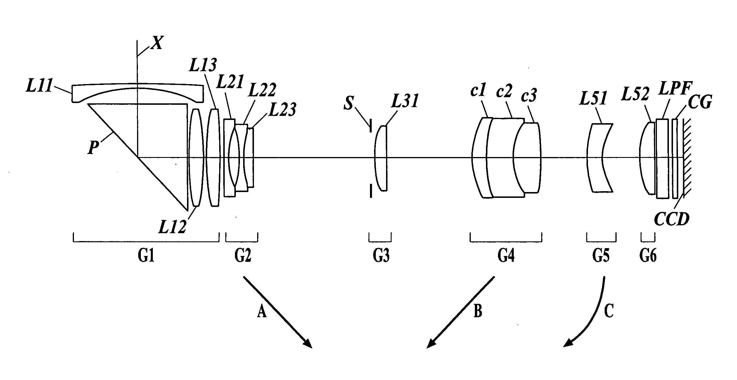
Figure 1 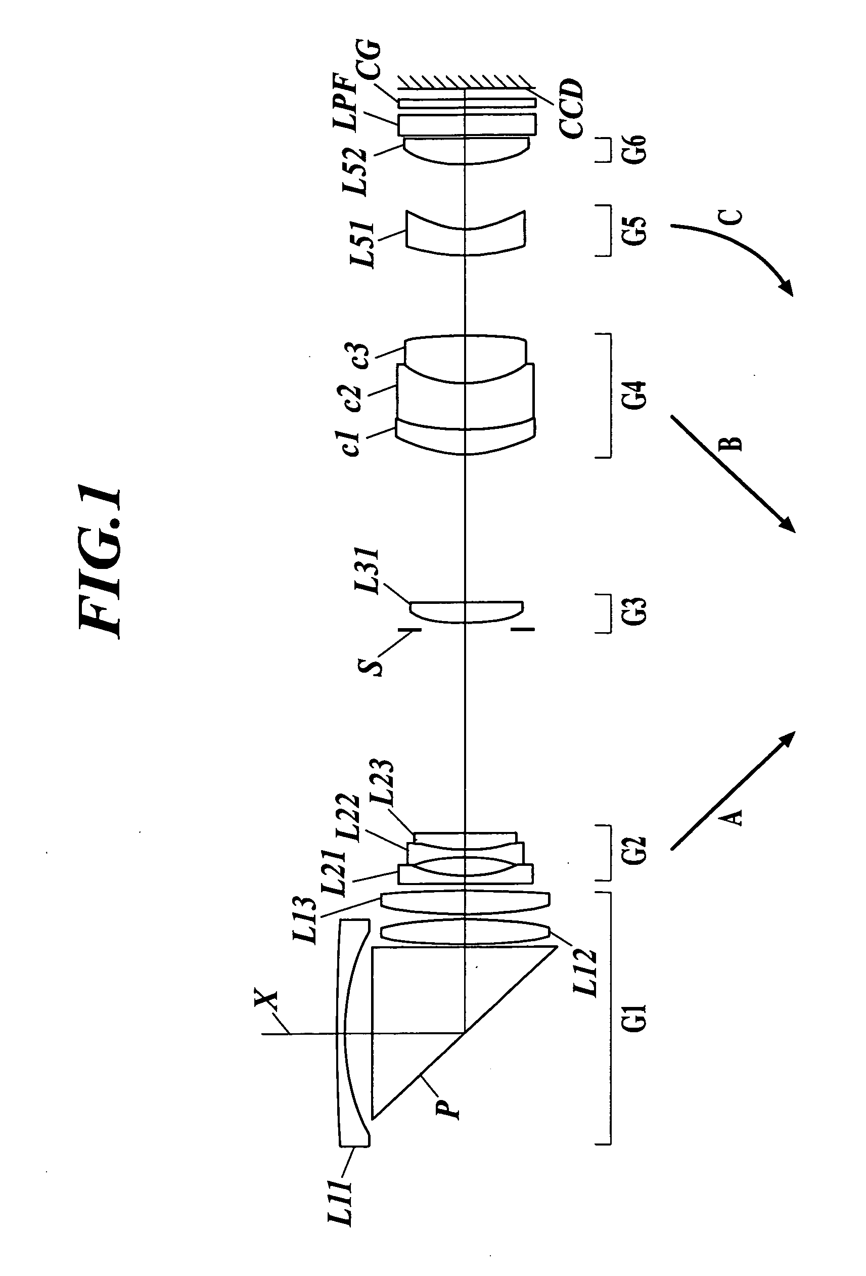
Figure 2 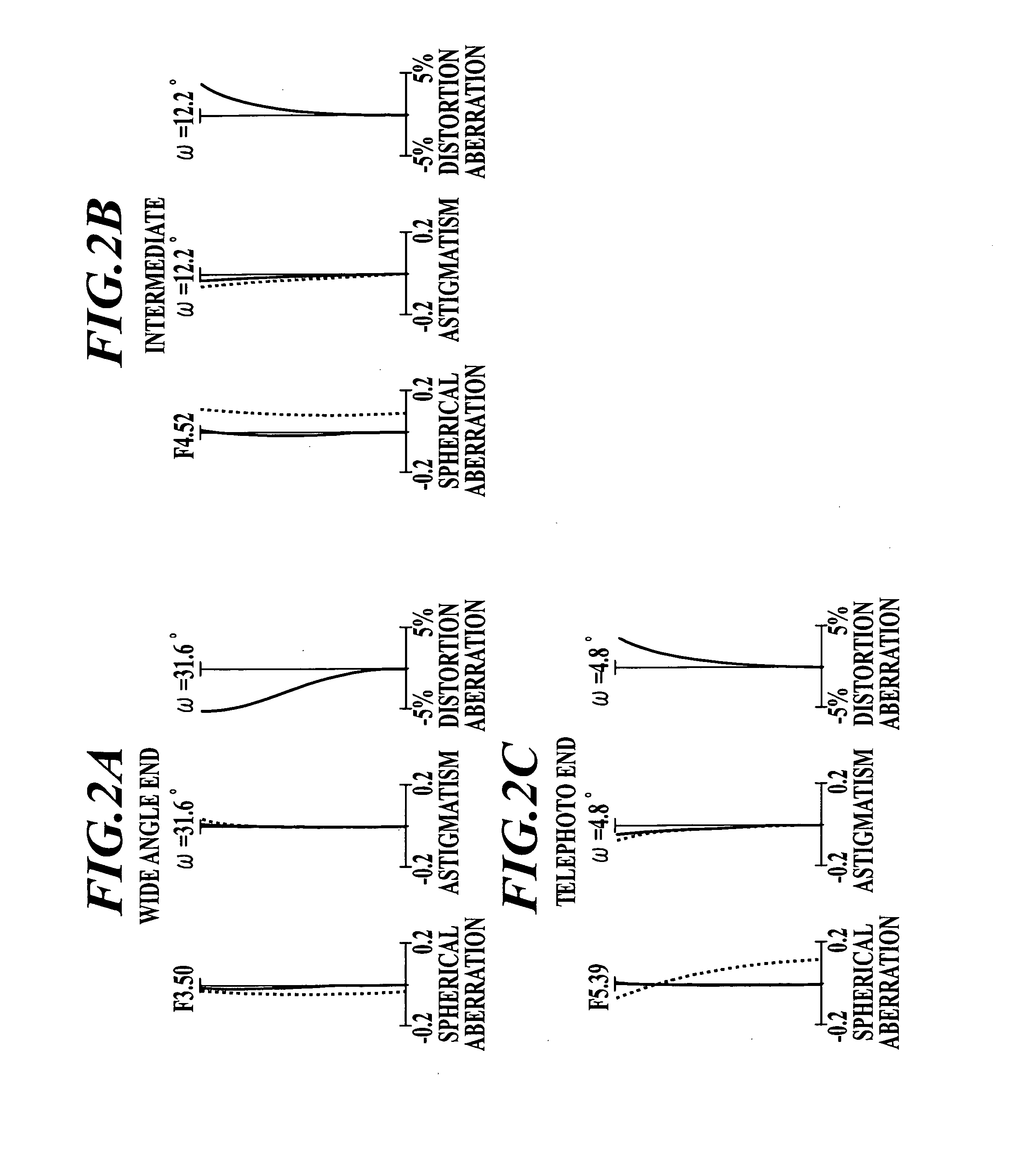
Figure 3
Abstract
Description
BACKGROUND OF THE INVENTION
[0001] 1. Field of the Invention
[0002] The present invention relates to a zoom lens and an image pickup apparatus. The present invention relates to a zoom lens and an image pickup apparatus for a charge-coupled device (CCD) or a complementary metal oxide semiconductor (CMOS) that are used for a digital camera or a video camera for example, that have a variable power ratio of about 5 to 7 and a field angle of at a wide angle end equal to or higher than 60°, and that can reduce the thickness of the camera.
[0003] 2. Description of Related Art
[0004] A digital still camera or a video camera using a CCD or a CMOS highly requires a type of a lens by which the thickness of the camera can be reduced in particular. Recently, such a camera also requires a more sophisticated optical specification such as a further higher variable power ratio. A kind of a camera having a thin thickness frequently uses a bending optical system that bends an optical axis by 90 degree...
Examples
embodiment 1
Illustrative Embodiment 1
[0200] Table 2 shows lens data for a zoom lens according to Illustrative Embodiment 1. FIG. 1 is a cross-sectional view at a wide angle end of the zoom lens according to Illustrative Embodiment 1. FIGS. 2A to 2C are aberration diagrams illustrating the spherical aberration, astigmatism, and distortion aberration of the zoom lens according to Illustrative Embodiment 1. Here, FIG. 2A is an aberration diagram at a wide angle end. FIG. 2B is an aberration diagram at an intermediate part. FIG. 2C is an aberration diagram at a telephoto end. In the following description, these aberration diagrams will be described based on an assumption that the solid line and the dotted line in the spherical aberration diagram represent the d-line and the g-line, respectively and the solid line and the dotted line in the astigmatism diagram represent a sagittal field and a meridional field, respectively.
TABLE 2ILLUSTRATIVE EMBODIMENT 1SURFACE NO.R(mm)d(mm)ndνd 1101.0040.601.846...
embodiment 2
Illustrative Embodiment 2
[0203] The lens data of the zoom lens of Illustrative Embodiment 2 is shown in Table 3. FIG. 3 is a cross-sectional view at a wide angle end of the zoom lens of Illustrative Embodiment 2. FIGS. 4A to 4C are aberration diagrams illustrating the spherical aberration, astigmatism, and distortion aberration of the zoom lens according to Illustrative Embodiment 2. Here, FIG. 4A is an aberration diagram at a wide angle end. FIG. 4B is an aberration diagram at an intermediate part. FIG. 4C is an aberration diagram at a telephoto end.
TABLE 3ILLUSTRATIVE EMBODIMENT 2SURFACE NO.R(mm)d(mm)ndνd 194.0070.601.8466623.8 217.0051.75 3∞12.551.9036631.32 4∞0.20 549.0461.631.4970081.6 6−41.0630.20 728.0351.751.7725049.6 8−61.414d1 (CHANGEABLE) 9−51.5890.551.8340037.2109.7721.4111−11.6980.501.7725049.61215.7751.431.9228620.913−29.690d2 (CHANGEABLE)1413.9131.471.5891361.21558.613d3 (CHANGEABLE)167.9162.261.4970081.61712.5873.151.9228620.9186.3713.121.5831359.419927.306d4 (CHAN...
embodiment 3
Illustrative Embodiment 3
[0206] The lens data of the zoom lens of Illustrative Embodiment 3 is shown in Table 4. FIG. 5 is a cross-sectional view at a wide angle end of the zoom lens of Illustrative Embodiment 3. FIGS. 6A to 6C are aberration diagrams illustrating the spherical aberration, astigmatism, and distortion aberration of the zoom lens according to Illustrative Embodiment 3. Here, FIG. 6A is an aberration diagram at a wide angle end. FIG. 6B is an aberration diagram at an intermediate part. FIG. 6C is an aberration diagram at a telephoto end.
TABLE 4ILLUSTRATIVE EMBODIMENT 3SURFACE NO.R(mm)d(mm)ndνd 1130.6950.601.8466623.8 217.7241.98 3∞11.921.9036631.32 4∞0.20 591.8331.871.4970081.6 6−21.6520.20 717.9951.921.7291654.7 8−559.659d1 (CHANGEABLE) 9−59.2820.551.8830040.8109.6741.0811−13.8060.501.7291654.7129.7011.281.9228620.913369.171d2 (CHANGEABLE)1412.6411.481.5831359.41548.845d3 (CHANGEABLE)169.4451.301.4874970.21716.3034.491.8466623.8186.6004.121.5831359.419−27.769d4 (CHA...