Photo printer with a vertically transmitted platen roller

a technology of platen roller and platen printer, which is applied in the field of photo printers, can solve the problems of unavoidable use of metal frames and higher manufacturing costs

Inactive Publication Date: 2007-03-29
LITE ON TECH CORP
View PDF4 Cites 13 Cited by
  • Summary
  • Abstract
  • Description
  • Claims
  • Application Information

AI Technical Summary

Problems solved by technology

In addition, since the platen roller frame or the TPH frame moves the platen roller or the TPH via a torque, significant rigidity of t

Method used


Image

  • Photo printer with a vertically transmitted platen roller
  • Photo printer with a vertically transmitted platen roller
  • Photo printer with a vertically transmitted platen roller

Examples


Embodiment Construction

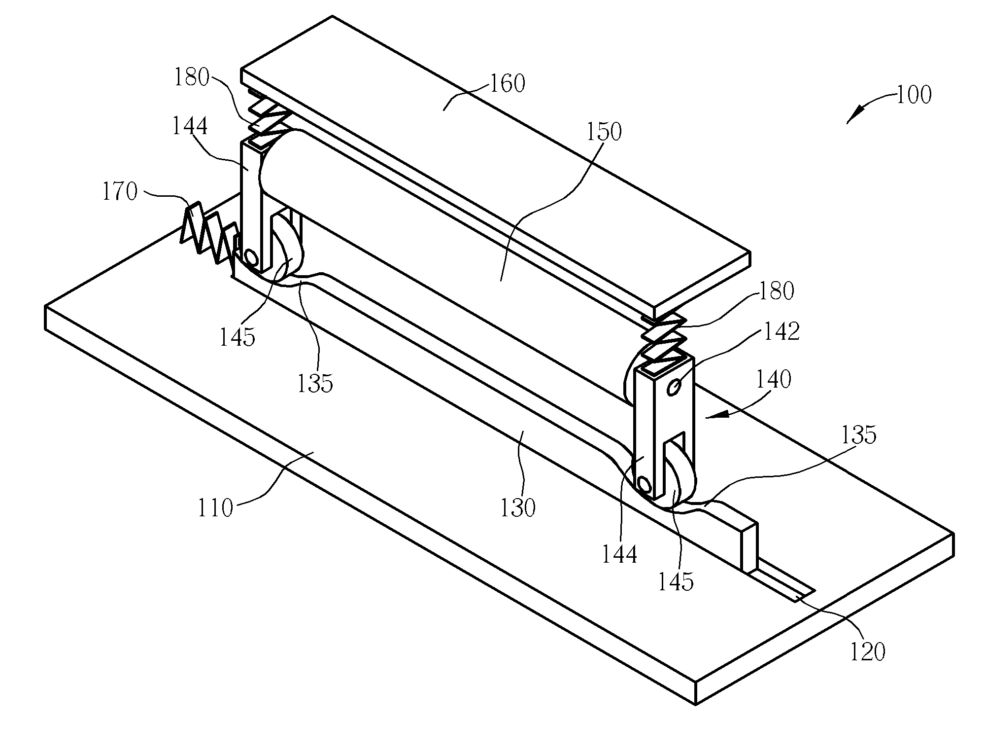
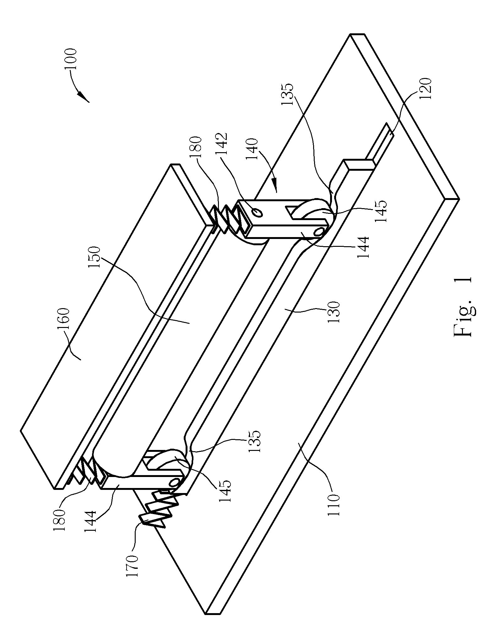
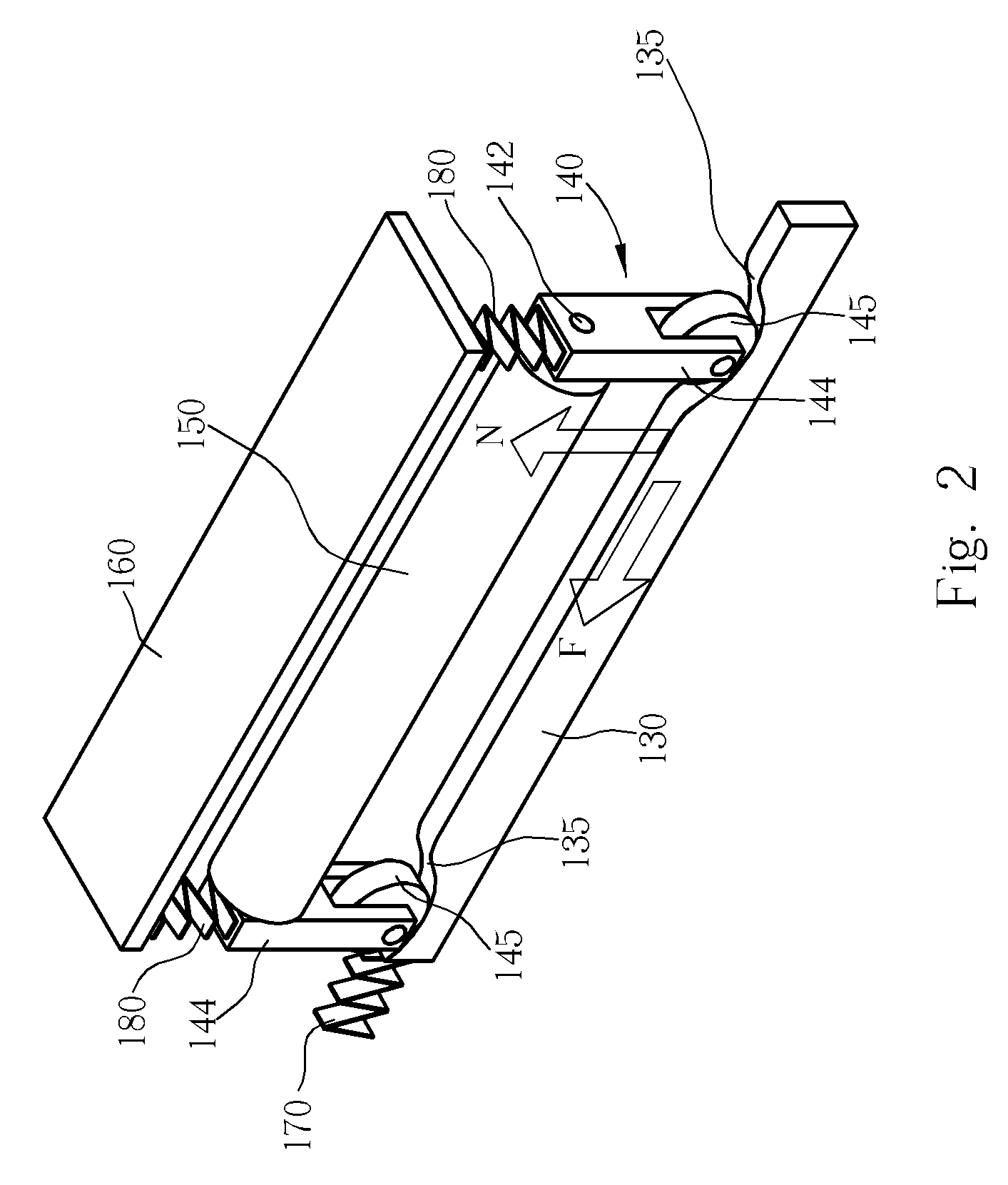
[0014] Please refer to FIG. 1, which is an illustration of a photo printer 100 with a mechanism that can move a platen roller 150 vertically. The photo printer 100 comprises a housing 110 with a track 120, a translating cam 130 having a plurality of concave surfaces 135, a platen roller frame 140, a platen roller 150, a print head 160, and elastic elements 170, 180. The platen roller frame 140 includes two pin frames 144, each comprising a spindle bore 142 and a roller 145.

[0015] The translating cam 130 is installed at a horizontal displacement along the track 120, and the platen roller frame 140 is installed on the translating cam 130. The platen roller 150 is rotatably installed on the platen roller frame 140 with the spindle bore 142 of each pin frame 144 for receiving the platen roller 150, allowing the platen roller 150 to rotate along an axle of the platen roller 150 on the platen roller frame 140. The print head 160 is disposed on one side of the platen roller 150 for printi...


PUM


Abstract

In a photo printer, with a translating cam at a horizontal displacement, a platen roller can be lifted up/down vertically to/from a print head. On the profile of the translating cam, there is plurality of concave surfaces and a convex surface as a follower's path. A platen roller frame is used for supporting the platen roller. As the translating cam moves in the track, the roller installed on the platen roller frame rotates on the translating cam's profile. Following the variation of the translating cam's profile, the platen roller frame carries the platen roller to move vertically, so that the platen roller can move to/from the print head in straight line.

Description

BACKGROUND OF THE INVENTION [0001] 1. Field of the Invention [0002] The present invention relates to a photo printer, and more specifically, to a photo printer with a vertically transmitted platen roller. [0003] 2. Description of the Prior Art [0004] A thermal printing head (TPH) and a platen roller for carrying a print medium are two necessary parts in a dye-sublimation / thermal photo printer. These two parts are not contacting with each other when the photo printer is not printing but contacting and generating a contact force when the photo printer is printing. The contact force due to the mutual thrust of the TPH and the platen roller ensures that the inserted print medium is grabbed by the TPH and the platen roller and that the TPH can contact the print medium to sublimate dye onto the print medium. [0005] The mechanism that draws the TPH and the platen roller close in a thermal photo printer in the prior art can be classified into two major classes. As disclosed in Japanese publ...

Claims


Application Information

Patent Timeline
IPC IPC(8): B41J11/20B41J11/04
CPCB41J11/20B41J11/04
Inventor HO, HUI-CHUN
Owner LITE ON TECH CORP
Why Eureka
Try Eureka