Pedal angle adjustable device for exercisers

a technology of adjustable device and exerciser, which is applied in the direction of cardiovascular exercise device, gymnastic exercise, sport apparatus, etc., can solve the problem of difficult task for most uses, and achieve the effect of improving the stability and stability

Inactive Publication Date: 2007-03-29
LIN MICHAEL
View PDF4 Cites 42 Cited by
  • Summary
  • Abstract
  • Description
  • Claims
  • Application Information

AI Technical Summary

Benefits of technology

[0005] The present invention will become more obvious from the following description when taken in connection with the accompanying drawings which show, for purposes of illustration only, a preferred embodiment in accordance with the present invention.

Problems solved by technology

This is obviously a difficult task for most of the uses.

Method used


Image

  • Pedal angle adjustable device for exercisers
  • Pedal angle adjustable device for exercisers
  • Pedal angle adjustable device for exercisers

Examples


Embodiment Construction

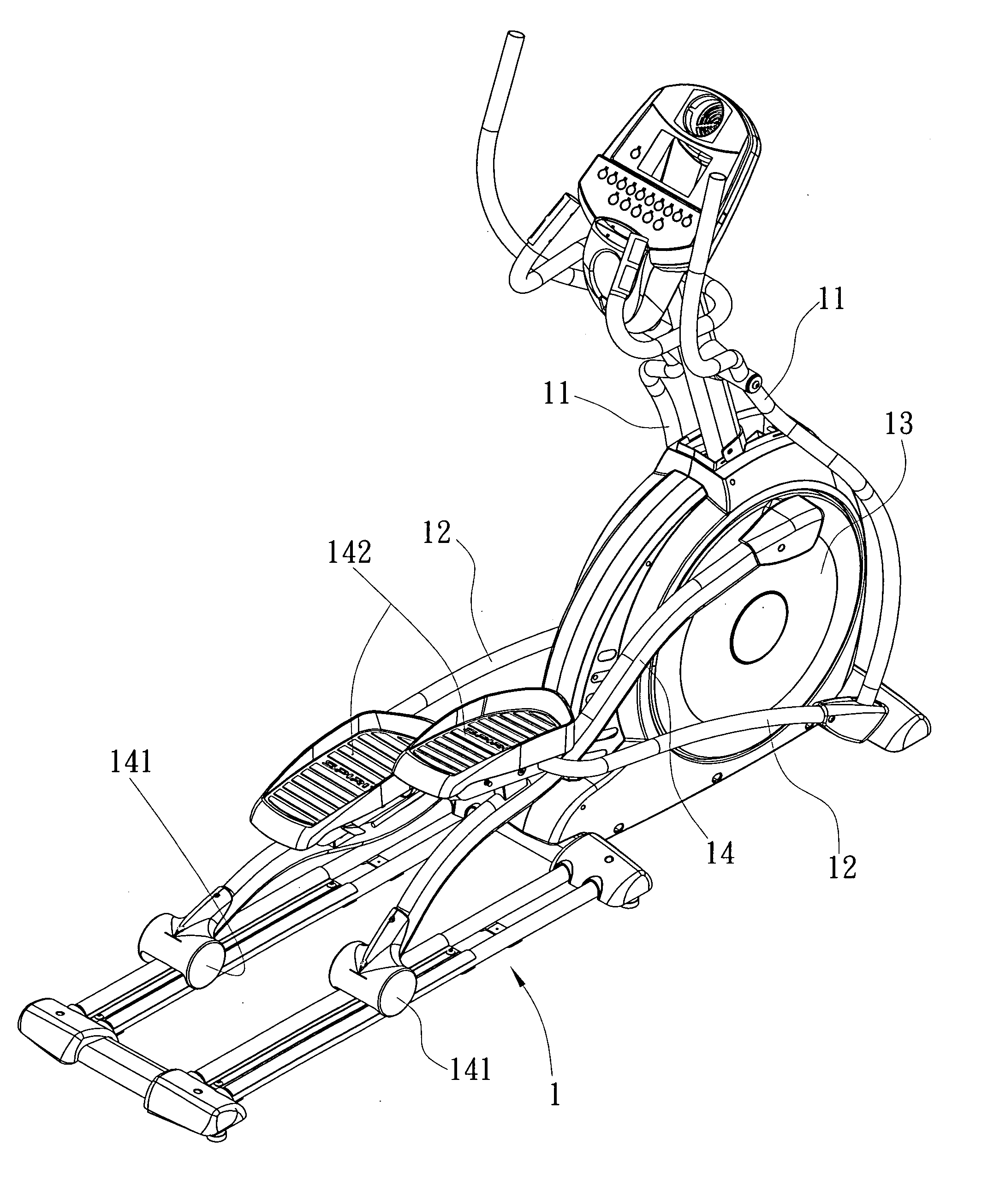
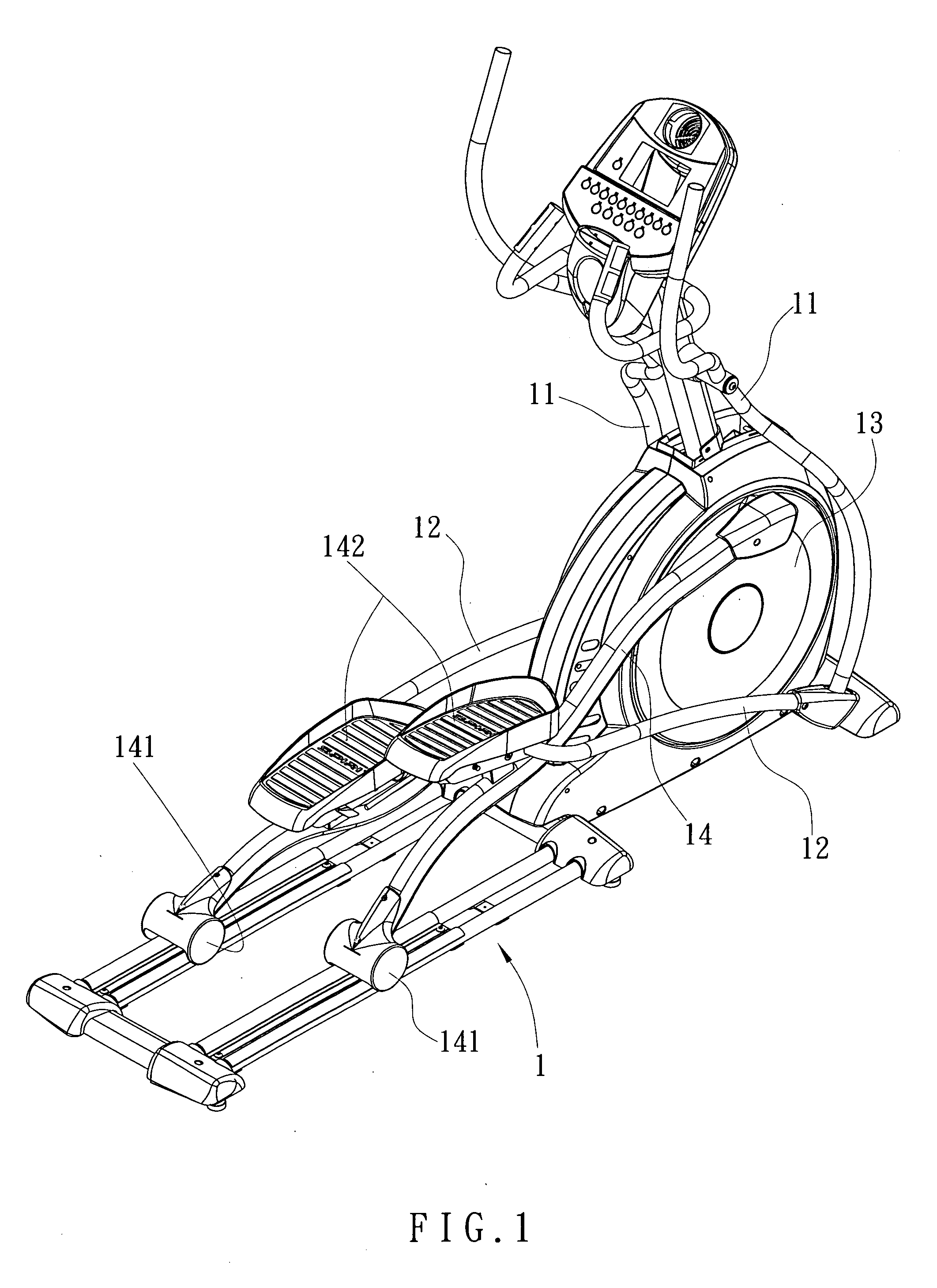
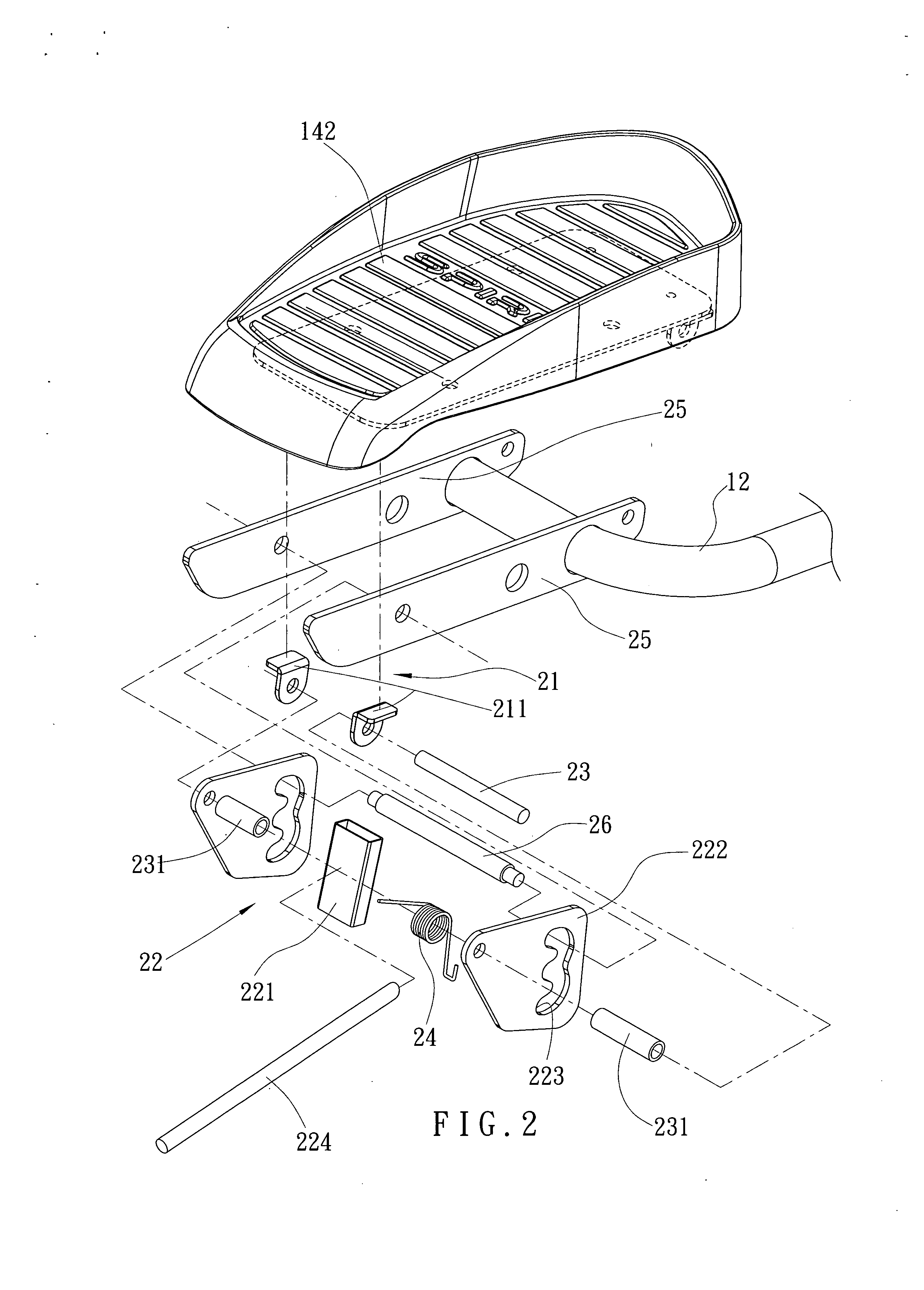
[0015] Referring to FIGS. 1 to 3, an elliptical trainer with the pedal adjustable device of the present invention comprises a base 1 with two rails at one end and a magnet wheel 13 at the other end of the base 1. Two swing bars 11 are pivotably connected to the base 1 and two pedal rods 12 are pivotably connected to two respective lower ends of the two swing bars 11. Two links 14 each have an end pivotably connected to the magnetic wheel 13 and the other end of each link 14 has a roller 141 which is movably engaged with the rails of the base 1. Two connection plates 25 are pivotably connected to a bending portion of each of the pedal rods 12 and respective one of two pedals 142 is connected to two respective ends the two connection plates 25. A tube is connected between the two connection plates 25 and fixed to an upright portion on each of the links 14, a pin extends through the two connection plates 25 and the tube so as to pivotably connect the two connection plates 25 to the lin...


PUM


Abstract

A pedal angle adjustable device for an elliptical trainer includes two adjustable plates pivotably connected between the pedal and two connection plates which are pivotably connected to an end of the pedal. The two adjustable plates each have a positioning hole composed of a plurality of positioning notches and a positioning rod extends through the two connection plates and the positioning holes in the two positioning plates. A push block connected to a handle is located in front of the positioning rod such that when operating the handle, the push block may push the positioning rod from one positioning notch to another and the pedal can be pivoted about the pivotal point on the end of the pedal.

Description

FIELD OF THE INVENTION [0001] The present invention relates to a pedal angle adjustable device for exercisers and the device is operated by a handle. BACKGROUND OF THE INVENTION [0002] A conventional pedal 6 for an exerciser such as an elliptical trainer is shown in FIGS. 10 and 11 and generally includes a connection member 61 which is connected to an underside of the pedal 6. The connection member 61 has three holes 611 defined therethrough. Two plates 7 are respectively and pivotably connected to a link connected to the magnetic wheel which is not shown. Each plate 7 has a slot 71 so that an adjustable pin 8 extends through the aligned slots 71 and one of the three holes 611 to position the angle of the peal 6 relative to the floor. However, when adjusting the pedal 6, the user has to pull the adjustable pin 8 out and hold the pedal 6 and move the pedal 6 till the desired hole 611 is in alignment with the two slots 71 of the plate 7, and the pin 8 is inserted into the alignment ho...

Claims


Application Information

Patent Timeline
Patent Type & Authority Applications(United States)
IPC IPC(8): A63B22/04
CPCA63B22/001A63B22/0015A63B2022/0676A63B22/0664A63B22/203A63B22/0046
Inventor CHEN, MING NAN
Owner LIN MICHAEL
Why Eureka
Try Eureka