Apparatus for delivering humidified gases

a technology of humidifier and apparatus, which is applied in the direction of medical atomisers, respirators, etc., can solve the problems of disconnecting patients and requiring separate electrical wiring connections

Inactive Publication Date: 2007-04-12
FISHER & PAYKEL HEALTHCARE LTD
View PDF51 Cites 96 Cited by
  • Summary
  • Abstract
  • Description
  • Claims
  • Application Information

AI Technical Summary

Benefits of technology

[0008] It is an object of the present invention to provide an apparatus for delivering humidified gases which at least goes some way towards overcoming the above disadvantages or which will at least provide the public with a useful choice.

Problems solved by technology

A disadvantage of these configurations is the need to disconnect the patient breathing conduit from the top of the humidifying chamber in a separate operation before removal of the chamber for the purpose of refilling.
A further disadvantage of these configurations is that separate electrical wiring connections are required to make use of a heated respiratory conduit.

Method used


Image

  • Apparatus for delivering humidified gases
  • Apparatus for delivering humidified gases
  • Apparatus for delivering humidified gases

Examples


Embodiment Construction

[0057] Embodiments of the present invention will now be described in more detail.

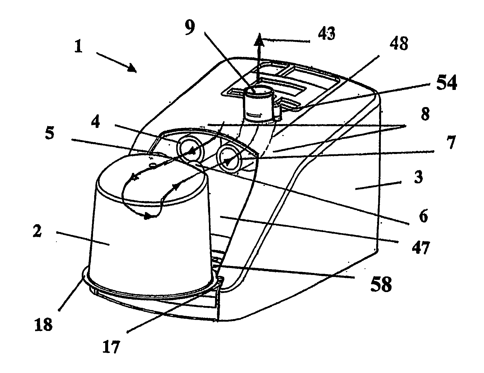
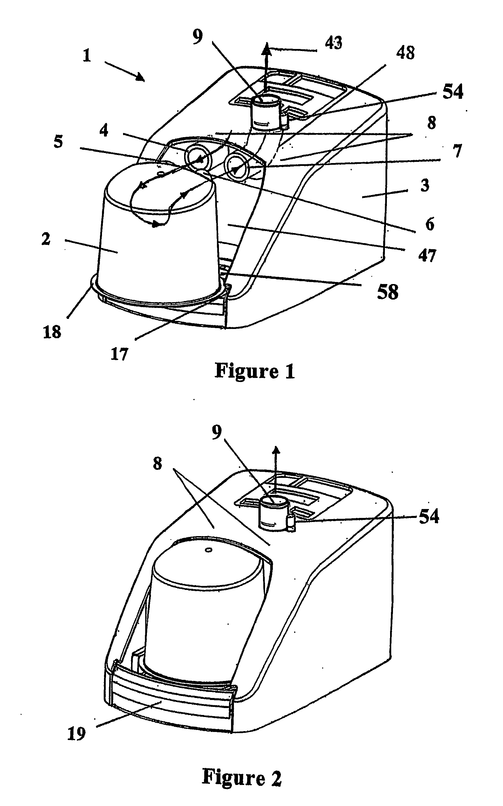
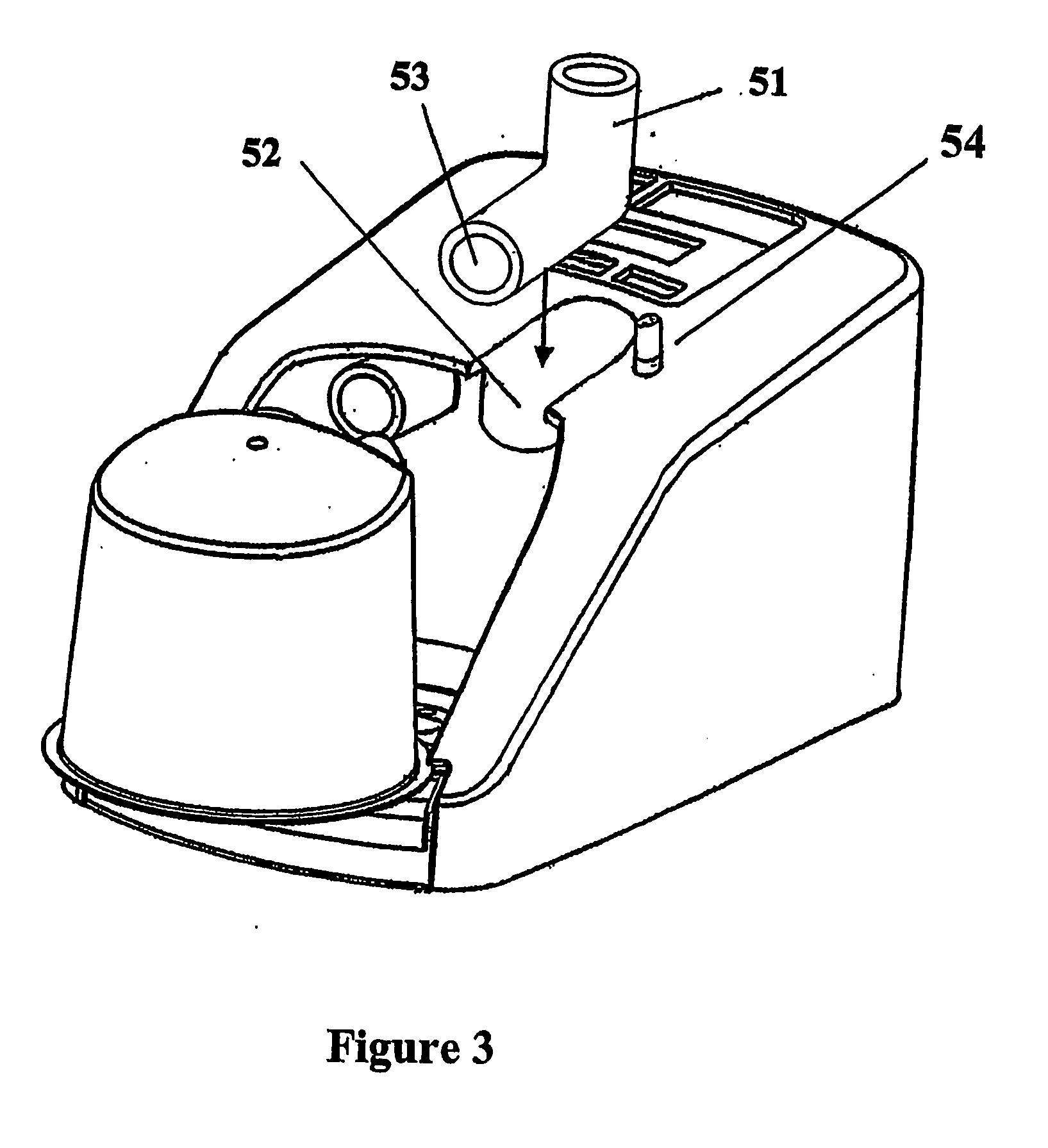
[0058] Referring to FIGS. 1 and 2, a preferred embodiment of the invention, in a CPAP machine has a housing containing a blower and a heater base, and a corresponding water chamber. A water chamber having a gases inlet port 5 and gases outlet port 6 is shown with a portable CPAP machine. The CPAP machine is adapted to receive slide-on humidifier chambers. The CPAP machine connects to the gases inlet / outlet ports of the water chamber through a connection manifold. Connection of the gases inlet and gases outlet ports are made to the connection manifold 8 of the CPAP machine in a single slide-on motion. The connection manifold 8 also provides an auxiliary outlet connection port 9 suitable for receiving a flexible respiratory conduit to deliver humidified air to a patient.

[0059] The CPAP machine includes a heater base 58 in a chamber receiving bay 47 to heat the water chamber. A securing arrangement is pr...


PUM


Abstract

An apparatus for delivering humidified gases has a connection manifold (8) adapted to connect with inlet (5) and outlet (6) ports of a slide-on water chamber (2) in a single slide on motion. Connection of the gases inlet (5) and gases outlet (6) ports as well as any additional electrical and/or pneumatic connections are all made in the same slide on motion. The water chamber (2) may include inwardly extending elongate extension tubes (30,31) and at least one of the extension tubes may also have an air bleed aperture (33) to aid filling of the chamber (2).

Description

BACKGROUND TO THE INVENTION [0001] i) Field of the Invention [0002] The present invention relates to apparatus for delivering humidified gases. In particular it relates to a humidifier arrangement for an integrated device providing respiratory assistance to patients, for example in consumer CPAP delivery devices. [0003] ii) Summary of the Prior Art [0004] Humidification systems are known which include a heater base and a disposable humidifier chamber which is fitted onto the heater base and within which a supply of water can be heated by the heater base. Air enters the humidifier chamber through an inlet air port in the roof of the chamber where it is humidified by the evaporation of water from the water supply before leaving the chamber through an exit port in the roof of the humidifier chamber. [0005] Humidifier chambers of this type are also now used in compact and portable ventilation machines, for example machines intended for the home treatment of obstructive sleep apnoea (CPA...

Claims


Application Information

Patent Timeline
Patent Type & Authority Applications(United States)
IPC IPC(8): A61M11/00A61M16/00A61M16/10A61M16/16
CPCA61M16/0066A61M16/16A61M16/109
Inventor KRAMER, MARTIN PAUL FRIEDRICHMAKINSON, IAN DOUGLASBIGGS, PHILIP JAMESDICKINSON, PHILIP JOHN
Owner FISHER & PAYKEL HEALTHCARE LTD
Why Eureka
Try Eureka