Phase reference generator with driving point voltage estimator

a technology of phase reference generator and driving point voltage, which is applied in the direction of electric variable regulation, process and machine control, instruments, etc., can solve the problems of limiting the performance of thyristor or silicon controlled rectifier (scr) based phase controller in general, affecting the accuracy of thyristor firing points, and insufficient method for generating time base for resistance welding applications. achieve the effect of improving the performance of resistance weld control, improving the tracking of driving point voltag

Inactive Publication Date: 2007-04-19
SCHNEIDER AUTOMATION INC
View PDF6 Cites 12 Cited by
  • Summary
  • Abstract
  • Description
  • Claims
  • Application Information

AI Technical Summary

Benefits of technology

[0012] The present invention substantially improves the performance of a resistance weld control's ability to track the driving point voltage (the open circuit voltage that would be observed if no current were flowing) by estimating in real time the driving point voltage waveform under all conditions. There is no longer the need to “freeze” the phase and frequency of the phase reference generator at initiation of a weld. The present system accomplishes this by assuming a simple circuit model for the power source and distribution system providing power to the weld control comprising an ideal, time varying driving point voltage source, a series line resistance and a series line reactance. Using the estimated parametric values of line resistance and line reactance, an estimated driving point volt-time area is computed and used in the conventional manner as the basis for generating a phase reference generator that automatically tracks the power source under all conditions.
[0013] According to one embodiment of the invention, the system estimates the driving point voltage magnitude and phase in an AC phase controlled resistance weld application relative to an internal phase reference generator. The system provides improved tracking of the driving point voltage phase while welding. This results in more accurate timing of thyristor firing points and consequently better current accuracy during a resistance welding operation. The system also provides improved run to run load impedance estimates, resulting in more accurate feed-forward control. The system also provides improved line voltage compensation while welding.

Problems solved by technology

A phenomenon that can limit the performance of thyristor or silicon controlled rectifier (SCR) based phase controllers in general, and resistance weld controllers in particular, is the distortion of the observed voltage waveform caused by the presence of line impedance when current flows.
However, this method is inadequate for generating a time base for resistance welding applications because the flow of current into the weld causes distortion in the zero-crossings of the voltage waveform as observed by the weld control at its terminals.
However, in certain circumstances, particularly those in which the current ramps from an initial value to a final value over a number of line cycles the performance, while better than a system without such compensation, is not as accurate as it could be.
This system is also not as accurate as it could be.

Method used


Image

  • Phase reference generator with driving point voltage estimator
  • Phase reference generator with driving point voltage estimator
  • Phase reference generator with driving point voltage estimator

Examples


Embodiment Construction

[0064] While this invention is susceptible of embodiments in many different forms, there is shown in the drawings and will herein be described in detail preferred embodiments of the invention with the understanding that the present disclosure is to be considered as an exemplification of the principles of the invention and is not intended to limit the broad aspect of the invention to the embodiments illustrated.

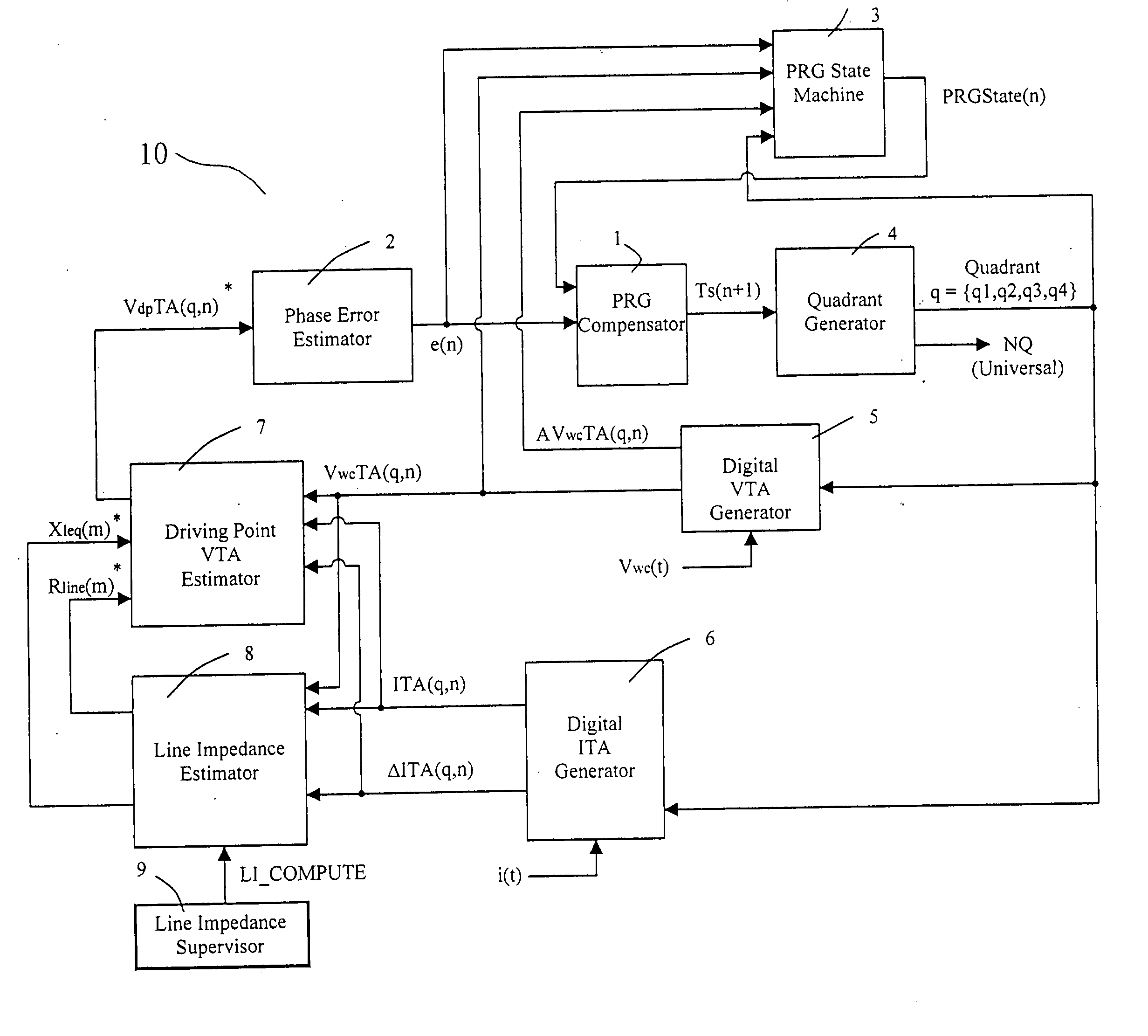
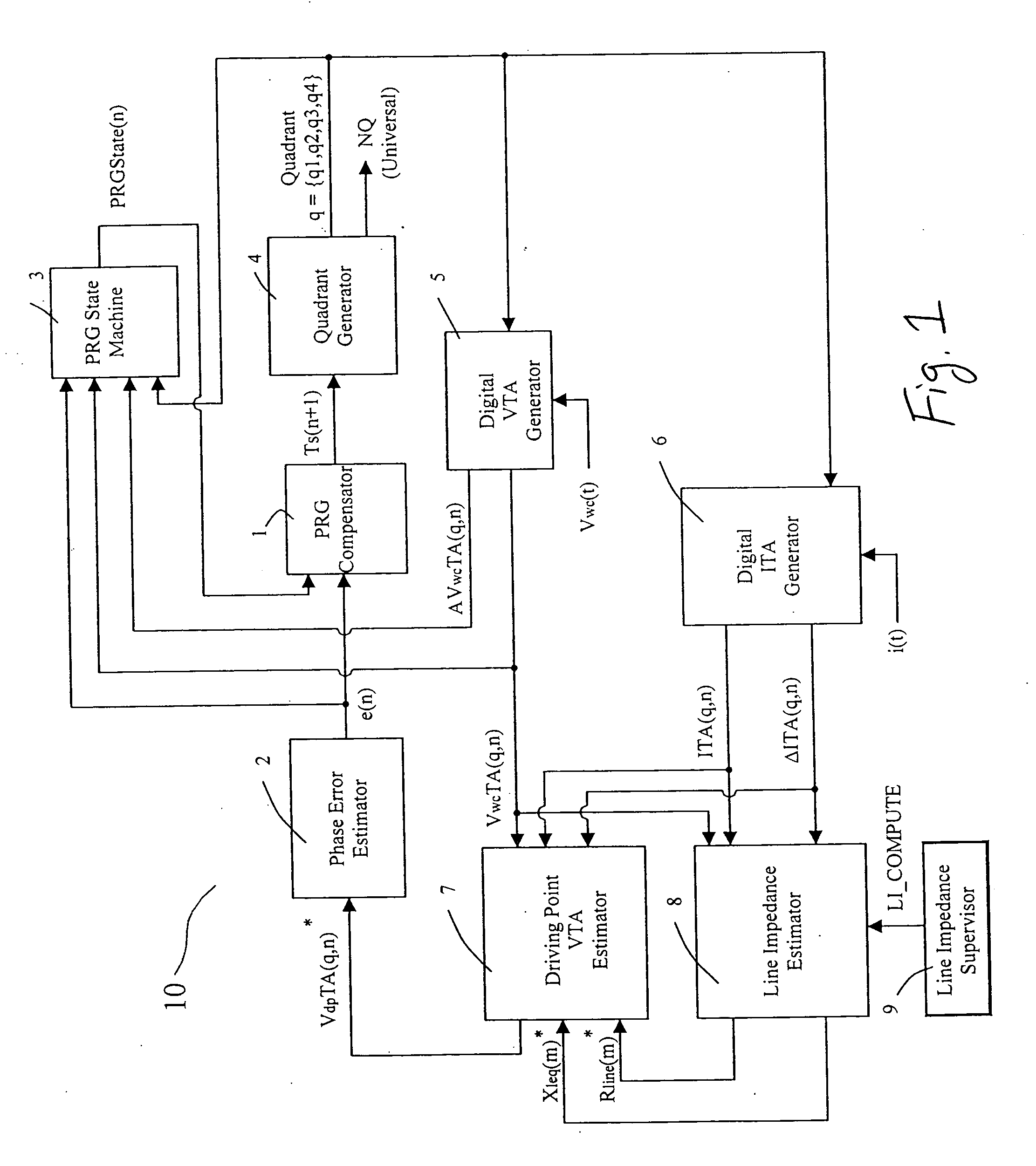
[0065] Referring to FIG. 1, a block diagram is disclosed of the components of a phase reference generator (“PRG”) 10 for providing improved tracking of a line voltage to create more accurate firing points of a resistance welding device. The present invention is preferably implemented in connection with a resistance weld control, such as the EQ5400 AC Resistance Weld Control sold by the Square D Company, to create a PRG timing cycle to match the driving point voltage of a power supply and distribution system. The EQ5400 AC Resistance Weld control can be modified to include the...


PUM

PropertyMeasurementUnit
voltageaaaaaaaaaa
frequencyaaaaaaaaaa
frequencyaaaaaaaaaa

Abstract

A phase reference generator for use in a resistance weld control. The phase reference generator including a digital signal processor having a digital volt-time area generator to generate a volt-time area of an observed voltage; a digital current-time area and current-difference-time area generator to generate a current-time area of an observed current and a current-difference-time area of the observed current; a line impedance estimator; and, a driving point voltage area estimator configured to receive values from the digital volt-time area generator, the digital current-time area generator and current-difference-time area generator, and the line impedance estimator and generate estimates of the driving point voltage.

Description

CROSS-REFERENCE TO RELATED APPLICATIONS [0001] The present application claims the benefit of Provisional Application No. 60 / 727,425 filed Oct. 17, 2005, the contents of which are incorporated herein by reference. The present application is being filed concurrently with U.S. patent application No. ______ (not yet assigned) entitled “Method And System For Estimating Driving Point Voltage” (Attorney Docket No.: SAA-128-2 (402P349)).FEDERALLY SPONSORED RESEARCH OR DEVELOPMENT [0002] N / A TECHNICAL FIELD [0003] The invention generally relates to a system and method for providing improved thyristor timing in AC phase controllers, and more particularly to a system and method for providing improved timing for resistance welding operations. BACKGROUND OF THE INVENTION [0004] A phenomenon that can limit the performance of thyristor or silicon controlled rectifier (SCR) based phase controllers in general, and resistance weld controllers in particular, is the distortion of the observed voltage w...

Claims


Application Information

Patent Timeline
Patent Type & Authority Applications(United States)
IPC IPC(8): G05F1/00
CPCB23K11/241B23K11/252B23K11/257B23K11/258
Inventor BUDA, PAUL R.
Owner SCHNEIDER AUTOMATION INC
Why Eureka
Try Eureka