Magnetic disk drive and magnetic head slider with stabilized flying

a magnetic disk drive and slider technology, applied in the direction of magnetic recording, information storage, maintaining head carrier alignment, etc., can solve the problems of physical and magnetic damage, ineffective magnetic disk drives disclosed in patent literatures 1 and 2, and deterioration of reliability of magnetic disk drives, etc., to achieve quick damping of translational, pitching and rolling vibrations

Inactive Publication Date: 2007-04-19
HITACHI GLOBAL STORAGE TECH NETHERLANDS BV
View PDF15 Cites 4 Cited by
  • Summary
  • Abstract
  • Description
  • Claims
  • Application Information

AI Technical Summary

Benefits of technology

[0021] According to the present invention it is possible to provide a magnetic disk drive and a magnetic head slider capable of quickly damping translational, pitching and rolling vibrations in the flying height direction of the magnetic head slider while stabilizing the flying of the magnetic head slider.

Problems solved by technology

However, the lowering of the flying height of the magnetic head slider increases the probability of contact between the magnetic head slider and the surface of the magnetic recording medium, with the result that the reliability of the magnetic disk drive may be deteriorated.
When the magnetic head slider vibrates largely in its flying height direction due to a shock from the exterior of the magnetic disk drive or due to an environmental change or when the magnetic head slider vibrates due to contact thereof with the magnetic recording medium, the magnetic disk drives disclosed in Patent Literatures 1 and 2 are not so effective.
However, when they are in continuous or strong contact with each other, it is very likely that one or both may suffer physical and magnetic damage.

Method used


Image

  • Magnetic disk drive and magnetic head slider with stabilized flying
  • Magnetic disk drive and magnetic head slider with stabilized flying
  • Magnetic disk drive and magnetic head slider with stabilized flying

Examples


first embodiment

[0041] A magnetic disk drive and a magnetic head slider according to a first embodiment of the present invention will be described below with reference to FIGS. 1 to 12.

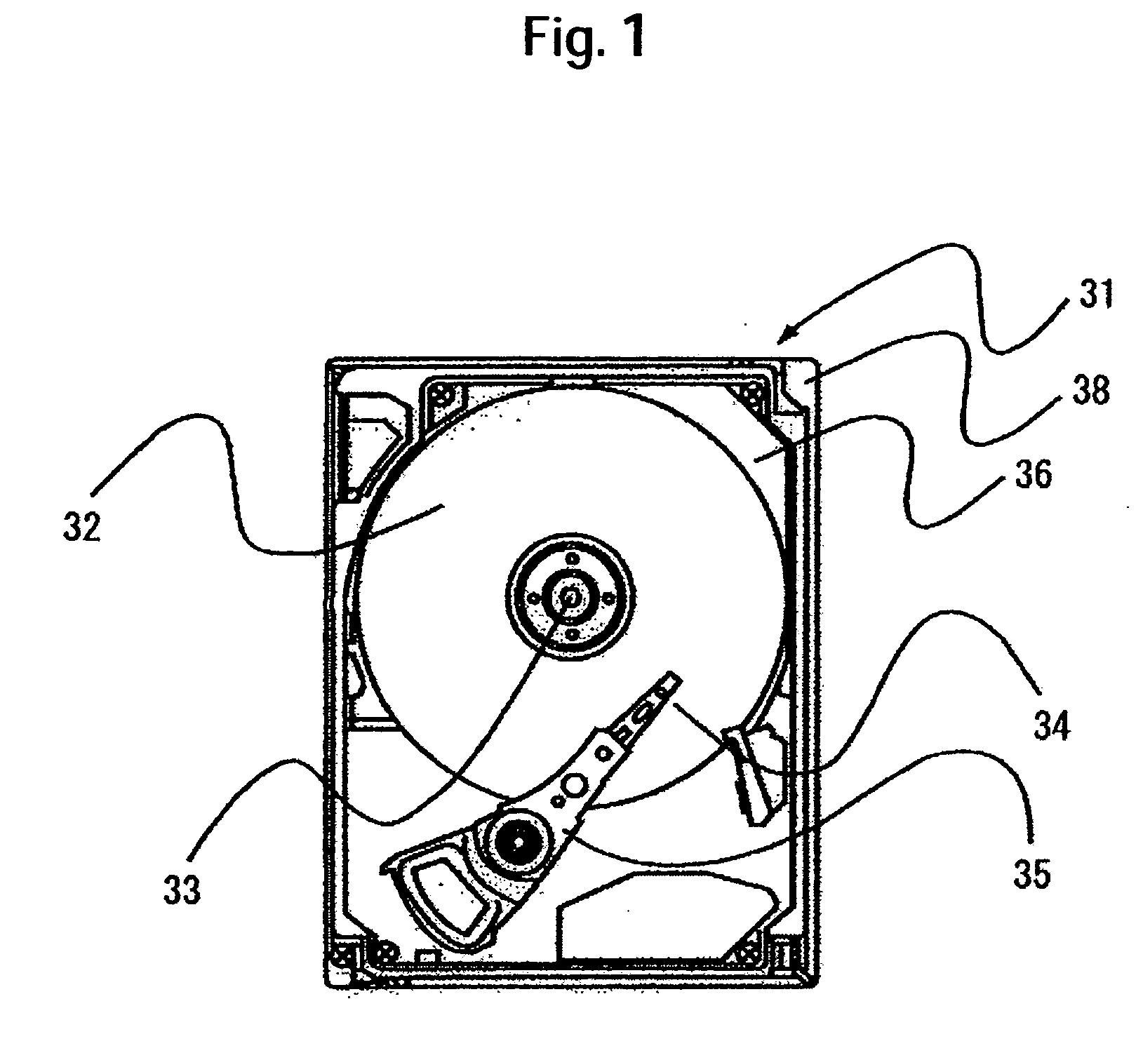
[0042] First, the overall construction of the magnetic disk drive according to this embodiment will be described with reference to FIG. 1. FIG. 1 is a plan view of the magnetic disk drive.

[0043] The magnetic disk drive, indicated at 31, includes a magnetic recording medium 32, a spindle motor 33, a magnetic head slider 34, an actuator 35, a case 36, a circuit board (not shown), and a buffer member 38.

[0044] The magnetic recording medium 32 is formed in the shape of a disc and has tracks onto which information is recorded. Under the action of an air flow created with rotation of the magnetic recording disk 32, the magnetic head slider 34 flies at a slight gap over a magnetic disk surface and reads information recorded on the magnetic recording medium 32 or writes information to the same medium. The actuator 35, whi...

second embodiment

[0064] Next, a second embodiment of the present invention will be described with reference to FIGS. 13 to 15. FIG. 13 is a diagram of a magnetic head slider 34 according to a second embodiment of the present invention as viewed from the air bearing surface side of the slider. FIG. 14 is a diagram showing calculation results of damping coefficients for a translational vibration in the flying height direction of magnetic head sliders on the basis of an air bearing surface model used in the second embodiment. FIG. 15 is a diagram showing calculation results of damping coefficients for a pitching vibration in the flying height direction of magnetic head sliders on the basis of the air bearing surface model used in the second embodiment. In FIGS. 14 and 15, frequency is plotted along the axis of abscissa and damping coefficient along the axis of ordinate.

[0065] This second embodiment is different in the following point from the first embodiment and is basically the same in the other poi...

third embodiment

[0068] Next, a third embodiment of the present invention will be described with reference to FIGS. 16 to 18. FIG. 16 is a diagram of a magnetic head slider according to a third embodiment of the present invention as viewed from the air bearing surface side of the slider. FIG. 17 is a plan view of an air bearing surface model for checkable calculation of the magnetic head slider 34 shown in FIG. 16. FIG. 18 illustrates calculation results of damping coefficients for a rolling vibration in the flying height direction of the magnetic head slider on the basis of the air bearing surface model used in this third embodiment. In FIG. 18, frequency is plotted along the axis of abscissa and damping coefficient along the axis of ordinate. A characteristic curve 29 indicated by a broken line represents the calculation result of a damping coefficient for a rolling vibration in the flying height direction of a magnetic head slider 34 not provided with the vibration suppressing groove 13. A charac...


PUM

PropertyMeasurementUnit
flying heightaaaaaaaaaa
natural frequencyaaaaaaaaaa
frequencyaaaaaaaaaa

Abstract

In a magnetic disk drive, translational and pitching vibrations in the flying height direction of a magnetic head slider are to be damped quickly while stabilizing the flying of the magnetic head slider. In one embodiment of the present invention, a magnetic disk drive is provided with a magnetic recording medium and a magnetic head slider adapted to fly over a surface of the magnetic recording medium and read or write information. The magnetic head slider includes a slider air bearing surface and a magnetic transducer. The slider air bearing surface includes a front pad having front rail surfaces and front step bearing surfaces, a rear pad having a rear rail surface and a rear step bearing surface, and a negative-pressure groove interposed between the front pad and the rear pad. A vibration suppressing groove is formed in the rear rail surface so as to be deeper than the rear rail surface and to be closed at its surround.

Description

CROSS-REFERENCES TO RELATED APPLICATIONS [0001] This application claims priority from Japanese Patent Application No. JP2005-266257, filed Sep. 14, 2005, the entire disclosure of which is incorporated herein by reference. BACKGROUND OF THE INVENTION [0002] The present invention relates to a magnetic disk drive and a magnetic head slider. [0003] A conventional magnetic disk drive reads or writes information while a magnetic head slider which carries a magnetic read / write head thereon flies over a rotating magnetic recording medium. When the flying magnetic head slider undergoes disturbance from the exterior of the magnetic disk drive or comes into contact with the rotating magnetic recording medium, it vibrates in its flying height direction. [0004] To attain higher density magnetic recording, the flying height of the magnetic head slider has been becoming increasingly low every year and at present the flying height is as low as near 10 nm. However, the lowering of the flying height ...

Claims


Application Information

Patent Timeline
Patent Type & Authority Applications(United States)
IPC IPC(8): G11B5/60
CPCG11B5/6005
Inventor SHIMIZU, YUKIXU, JUNGUOLI, JIANHUAYAMAZAKI, TAKANORI
Owner HITACHI GLOBAL STORAGE TECH NETHERLANDS BV
Why Eureka
Try Eureka