Hammer having a side working face

a side working face and hammer technology, applied in the field of hammers, can solve the problems of difficult to keep the nail accurately in position, unsuitable design of hammer,

Inactive Publication Date: 2007-04-26
CHEN YUNG SHOU
View PDF3 Cites 20 Cited by
  • Summary
  • Abstract
  • Description
  • Claims
  • Application Information

AI Technical Summary

Benefits of technology

[0006] The present invention has been accomplished under the circumstances in view. It is one object of the present invention to provide a hammer, which is practical for use in a narrow space for hammering. According to one aspect of the present invention, the hammer comprises a handle and a head fastened to one end of the handle. The head has a bell at one end, a claw at the other end

Problems solved by technology

However, this design of hammer is not suitable for driving a nail into a wall in a narrow space.
However, when

Method used


Image

  • Hammer having a side working face
  • Hammer having a side working face
  • Hammer having a side working face

Examples


Embodiment Construction

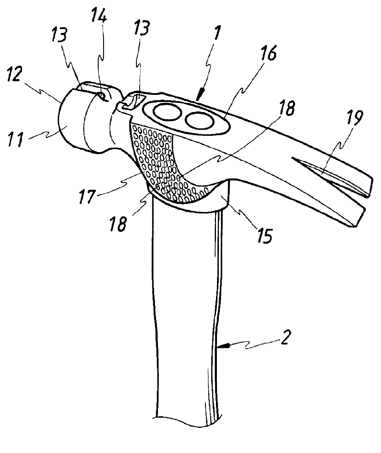
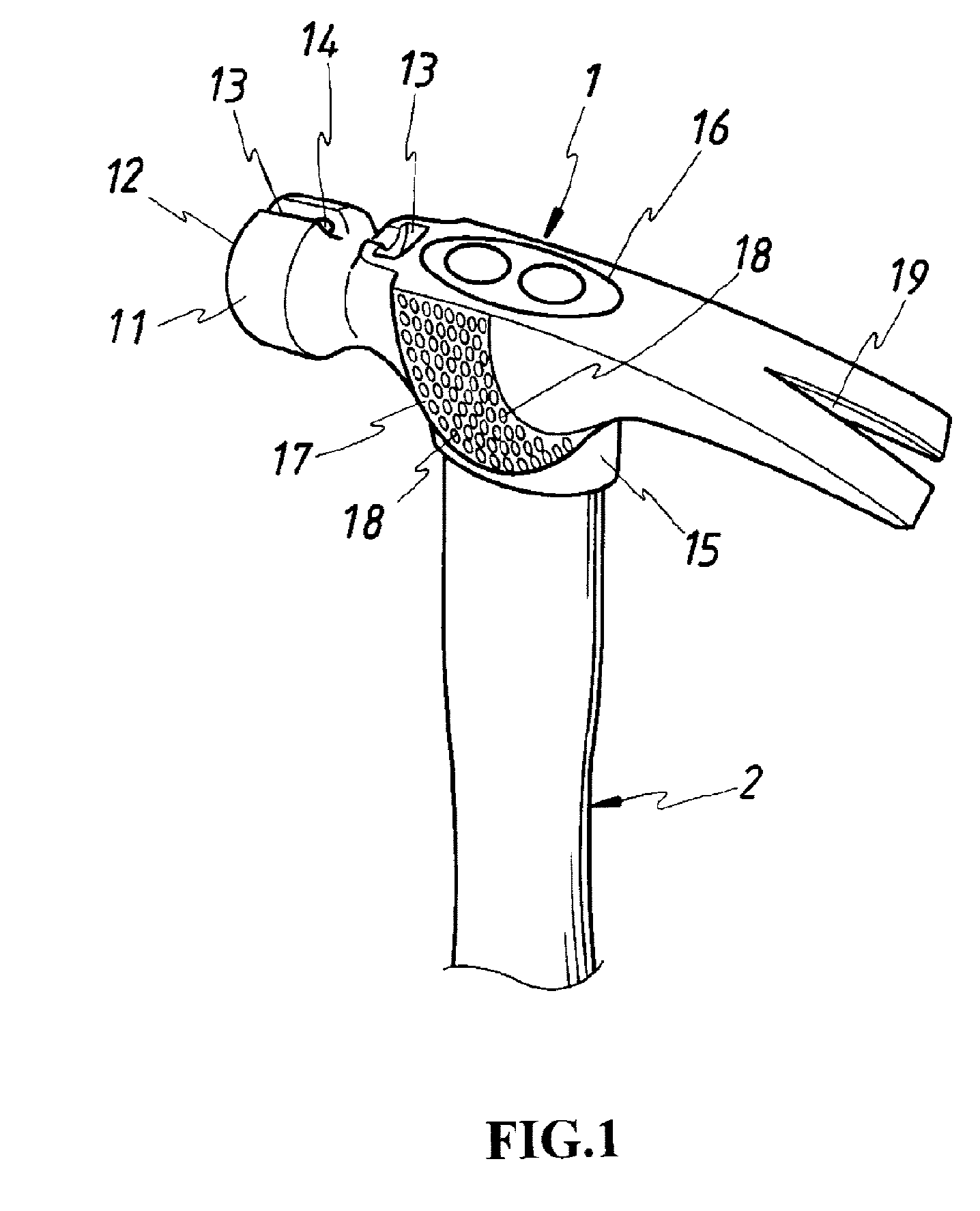
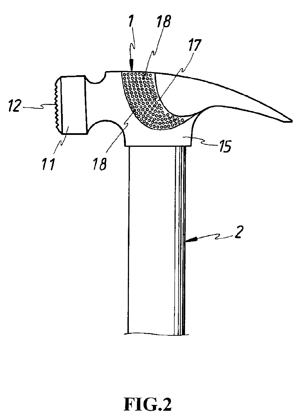
[0014] Referring to FIGS. 1˜3, a hammer in accordance with the present invention is shown comprising a handle 2 and a head 1 at one end of the handle 2. The head 1 has a bell 11 at one end, a nail groove 13 axially formed in the top side of the bell 11, a magnet 14 fixedly mounted in the nail groove 13, a claw 19 at the other end for extracting a nail, a coupling portion 15 on the middle between the bell 11 and the claw 19, a mounting through hole 16 cut through the top and bottom sides of the coupling portion 15 for receiving the handle 2, and at least one, for example, two side faces 17 at the opposite lateral sides of the coupling portion 16. The bell 11 has a coarse front face 12 for hammering. Each side face 17 has an anti-slip structure 18 to prevent slipping when hammering. The anti-slip structure 18 may be variously embodied. For example, the anti-slip structure 18 can be formed of raised and recessed portions, or intersected grooves. The handle 2 is fixedly fastened to the ...


PUM


Abstract

A hammer is disclosed, which has a nail groove axially formed in the top side of the front bell of the head thereof, a magnet mounted in the nail groove for attracting a metal nail for hammering, and a side face at each of the two opposite lateral sides of the head for hammering operations in a narrow space.

Description

BACKGROUND OF THE INVENTION [0001] (a) Field of the Invention [0002] The present invention relates to a hammer and more particularly, to such a hammer that has a side working face for hammering. [0003] (b) Description of the Prior Art [0004] A conventional hammer comprises a handle for grasping by the user, and a metal head fixedly fastened to one end of the handle. The metal head comprises a bell with a face at one end for driving a nail into a wall, and a claw at the other end for pulling a nail from the wall. [0005] Because the metal head of a conventional hammer has a bell at one end and a claw at the other end, it must have a certain dimension to provide a sufficient weight so that the metal head can efficiently drive a nail into a wall with less effort. However, this design of hammer is not suitable for driving a nail into a wall in a narrow space. A hammer may be made having two flat cheeks at two opposite lateral sides of the metal head for driving a nail into a wall by movi...

Claims


Application Information

Patent Timeline
IPC IPC(8): B25D1/00B25D1/06
CPCB25D1/045B25D1/06B25D1/14
Inventor CHEN, YUNG-SHOU
Owner CHEN YUNG SHOU
Why Eureka
Try Eureka