Small planar antenna with enhanced bandwidth and small strip radiator

a technology of conductive strip and small antenna, which is applied in the direction of antenna feed intermediates, resonance antennas, radiating element structural forms, etc., can solve the problems of reducing bandwidth, gain and efficiency, and large amount of conductive material for small antennas, so as to improve operative frequency bandwidth and improve radiation efficiency, gain and radiation efficiency. the effect of improving the bandwidth

Inactive Publication Date: 2007-05-03
SAMSUNG ELECTRONICS CO LTD
View PDF0 Cites 22 Cited by
  • Summary
  • Abstract
  • Description
  • Claims
  • Application Information

AI Technical Summary

Benefits of technology

[0015] Accordingly, an aspect of the present invention is to provide a planar small antenna which has an improved operative frequency bandwidth, and does not adversely affect radiation pattern, gain and radiation efficiency.
[0016] It is another aspect of the present invention to provide a small strip radiator which requires less metal or other conductive material than conventional radiators, and at the same time can operate without adversely affecting radiation characteristics.

Problems solved by technology

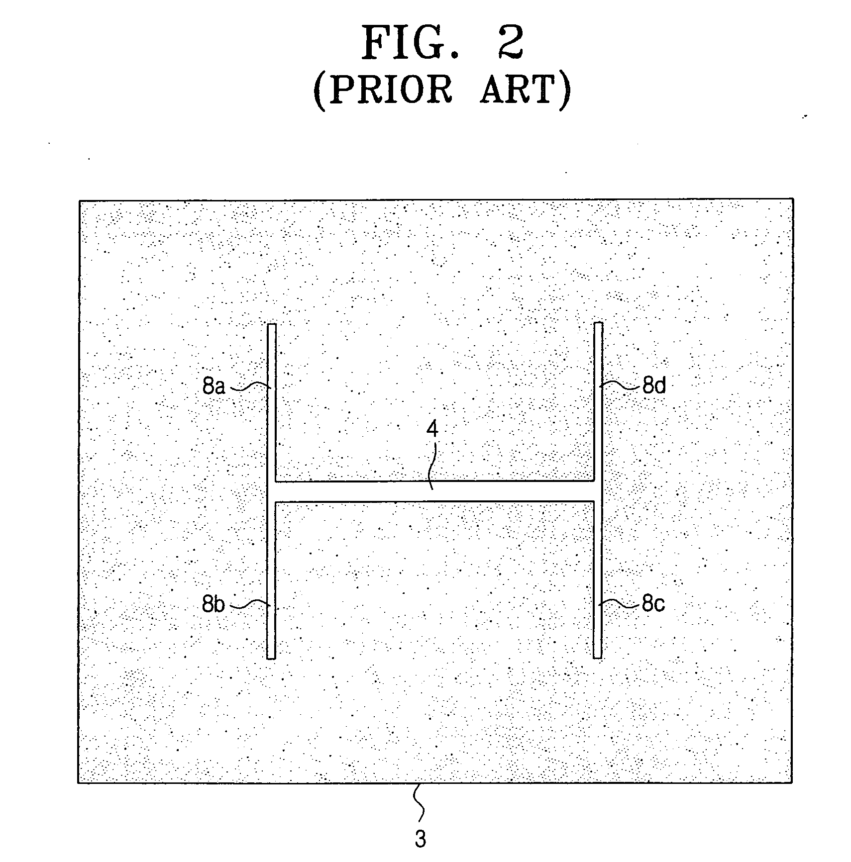
Of course, an antenna may be smaller than this size, but bandwidth, gain, and efficiency will decrease.
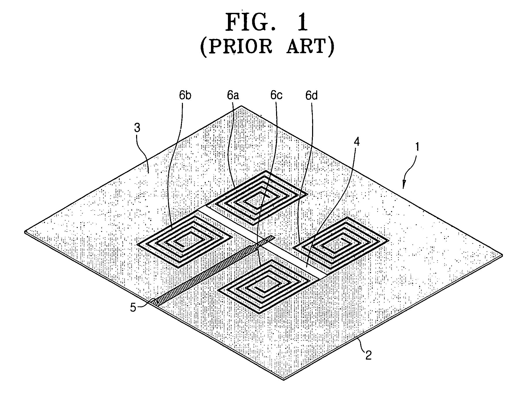
Meanwhile, a small antenna requires a large amount of conductive material for a ground layer.

Method used


Image

  • Small planar antenna with enhanced bandwidth and small strip radiator
  • Small planar antenna with enhanced bandwidth and small strip radiator
  • Small planar antenna with enhanced bandwidth and small strip radiator

Examples


Embodiment Construction

[0053] Exemplary embodiments of the present invention will be described herein below with reference to the accompanying drawings.

[0054]FIG. 5 is a perspective view of a planar small antenna according to an exemplary embodiment of the present invention. Referring to FIG. 5, a planar small antenna 100 according to an exemplary embodiment of the present invention includes a dielectric substrate 20, a metal layer 30 formed on an upper part of the dielectric substrate 20, a main slot 40 and a plurality of sub slots 60a, 60b, 70a, 70b, 80a, 80b, 90a, 90b which are patterned in the metal layer 30, and a feed line 50 which is formed at a lower part of the dielectric substrate 20. The metal layer 30 with the main slot 40 and the plurality of sub slots 60a, 60b, 70a, 70b, 80a, 80b, 90a, 90b form the radiator of the antenna 100.

[0055]FIG. 6 is a detailed plan view of the metal layer 30 which has the main slot 40 and sub slots 60a, 60b, 70a, 70b, 80a, 80b, 90a, 90b of FIG. 5. Hereinbelow, the...


PUM


Abstract

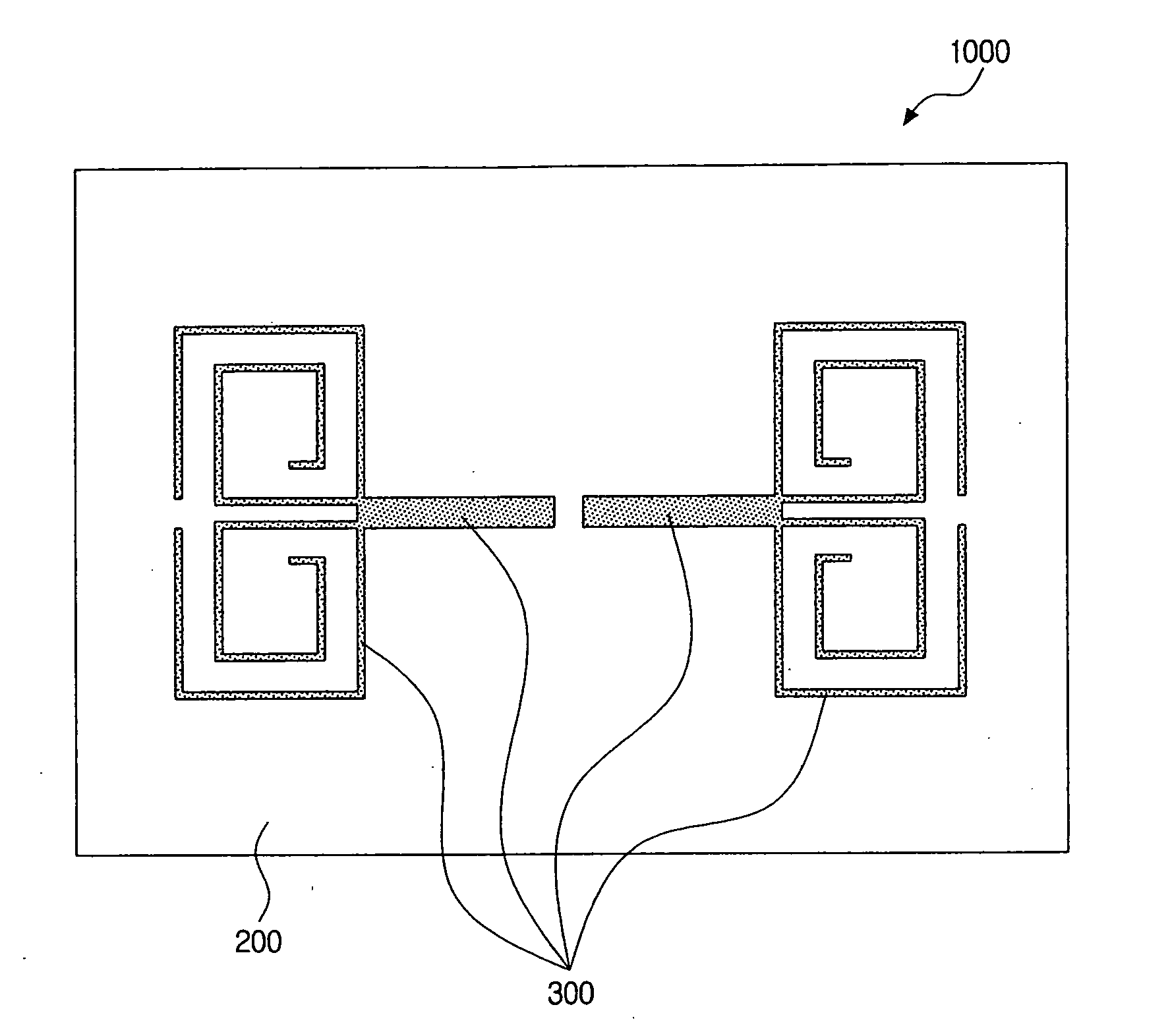
A planar small antenna and a small strip radiator are provided which have increased bandwidth. The small strip radiator has a main strip pattern and a plurality of convoluted strip patterns terminating the main strip pattern at each end. The plurality of convoluted strip patterns are arranged in mirror-symmetrical arrangement with reference to the longitudinal axis of the main strip such that one pair of convoluted strip patterns is convoluted clockwise while another pair is convoluted counterclockwise. As a result, an electrically small antenna radiator requires less metal or conductive material than conventional radiators, and also can operate without adversely affecting the radiation characteristics of the antenna.

Description

[0001] This is a divisional of application Ser. No. 11 / 207,725 filed Aug. 22, 2005. The entire disclosure of the prior application, application Ser. No. 11 / 207,725, is considered part of the disclosure of the accompanying divisional application and is hereby incorporated by reference.BACKGROUND OF THE INVENTION [0002] 1. Field of the Invention [0003] The present invention relates to RF and microwave antennas, and more particularly, to a small planar antenna and a small conductive strip radiator with improved bandwidth. [0004] 2. Description of the Related Art [0005] In L-frequency bandwidth and at UHF frequencies, the size of a half wave dipole antenna presents a restriction in mobile or RFID applications, and therefore, a small antenna with relatively small wavelength is required. However, the size of antenna for a given application is not related mainly to the technology used, but is defined by well-known laws of physics. Namely, the antenna size with respect to the wavelength is ...

Claims


Application Information

Patent Timeline
Patent Type & Authority Applications(United States)
IPC IPC(8): H01Q1/38H01Q1/36H01Q9/04H01Q9/27H01Q13/10H01Q13/16
CPCH01Q1/38H01Q9/285H01Q5/371H01Q5/28H01Q13/10
Inventor TIKHOV, YURIMIN, YOUNG-HOONKIM, YONG-JIN
Owner SAMSUNG ELECTRONICS CO LTD
Why Eureka
Try Eureka