
Plasma display panel and driving method thereof

a technology of display panel and plasma, which is applied in the direction of instruments, static indicating devices, etc., can solve the problems of too short sustained interval to make a display itself, brightness degradation, etc., and achieve the effect of high-speed addressing

Inactive Publication Date: 2007-05-10
LG ELECTRONICS INC
View PDF11 Cites 5 Cited by
  • Summary
  • Abstract
  • Description
  • Claims
  • Application Information

AI Technical Summary

Benefits of technology

This approach enables high-speed addressing, improves picture brightness, and allows for an increased number of sub-fields in a fixed frame interval, addressing the limitations of conventional PDPs by optimizing the address and sustaining intervals.

Problems solved by technology

Moreover, in the case of a high-resolution PDP having a very large number of scanning / sustaining electrode lines Y, a sustaining interval is too shortened to make a display itself.
As a result, a sustaining interval is inevitably reduced during the fixed one frame interval to cause brightness deterioration.

Method used


Image

  • Plasma display panel and driving method thereof
  • Plasma display panel and driving method thereof
  • Plasma display panel and driving method thereof

Examples


Embodiment Construction

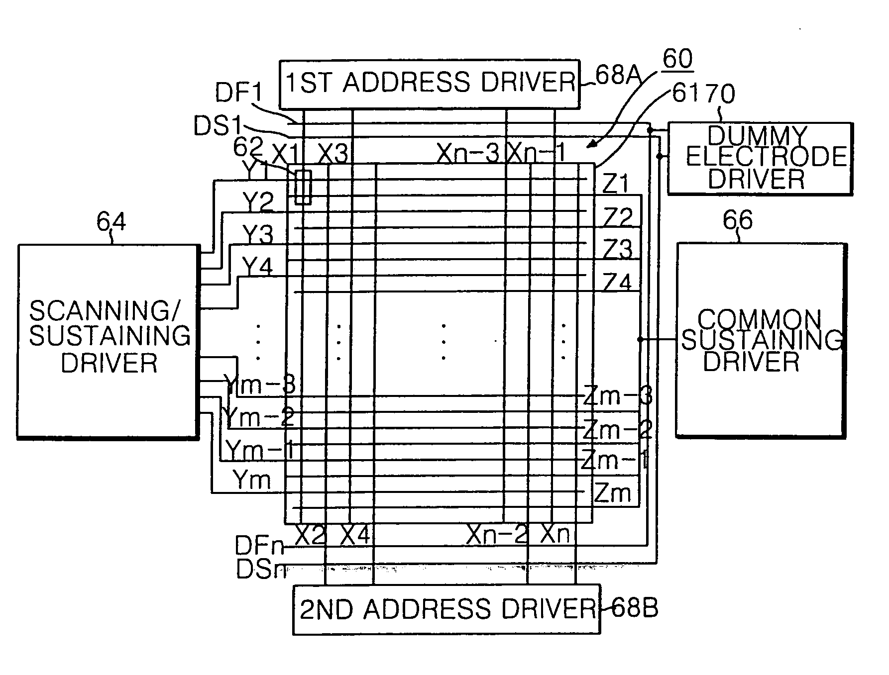
[0025] Referring to FIG. 5, there is shown a driving apparatus for a plasma display panel (PDP) according to an embodiment of the present invention. The PDP driving apparatus includes a PDP 60 having m×n discharge cells 62 arranged in a matrix type at each intersection among scanning / sustaining electrode lines Y, common sustaining electrode lines Z and address electrode lines X, dummy electrodes DF and DS provided at the upper and lower portions of an effective display part 61 of the PDP 60, a scanning / sustaining driver 64 for driving the scanning / sustaining electrode lines Y, a common sustaining driver 66 for driving the common sustaining electrode lines Z, first and second address driver 68A and 68B for making a divisional driving of the address electrode lines X into the odd-numbered lines and the even-numbered lines, and a dummy electrode driver 70 for driving the dummy electrode lines DF and DS. The scanning / sustaining driver 64 sequentially applies a scanning pulse to the scan...


PUM


Abstract

A plasma display panel that permits a high-speed addressing. In the panel, scanning / sustaining electrodes are provided at each discharge cell. Common sustaining electrodes are arranged in parallel to the scanning / sustaining electrodes at each discharge cell. At least two dummy electrodes are provided at the non-display area to supply the non-display area with charged particles in the address interval.

Description

CROSS-REFERENCE TO RELATED APPLICATIONS [0001] This application is a Continuation Application of prior U.S. patent application Ser. No. 11 / 298,934 filed Dec. 12, 2005, which is a Continuation application of prior U.S. patent application Ser. No. 09 / 748,118 filed Dec. 27, 2000 (now U.S. Pat. No. 6,975,285), which both claim priority under 35 U.S.C. §119 to Korean Application No. P1999-63225 filed on Dec. 28, 1999, which is hereby incorporated by reference.BACKGROUND [0002] 1. Field of the Invention [0003] This invention relates to a plasma display panel, and more particularly to a plasma display panel that permits a high-speed addressing. Also, the present invention is directed to a method of driving said plasma display panel. [0004] 2. Description of the Related Art [0005] Recently, a plasma display panel (PDP) feasible to a manufacturing of a large-dimension panel has been highlighted as a flat panel display device. The PDP typically includes a three-electrode, alternating current ...

Claims


Application Information

Patent Timeline
Patent Type & Authority Applications(United States)
IPC IPC(8): G09G3/28G09G3/288
CPCG09G3/293G09G3/2932G09G3/2948G09G3/2983G09G3/2986G09G2300/043G09G2310/0232G09G3/291G09G3/292
Inventor MYUNG, DAE JIN
Owner LG ELECTRONICS INC
Features
  • Generate Ideas
  • Intellectual Property
  • Life Sciences
  • Materials
  • Tech Scout
  • Unparalleled Data Quality
  • Higher Quality Content
  • 60% Fewer Hallucinations
Learn More