Display device
a display element and display technology, applied in the field of display devices, can solve the problems of image burn-in phenomenon and variations in luminance of pixels, and achieve the effect of suppressing the phenomenon of so-called “image burn-in” and reducing the variation of light emission of display elements
- Summary
- Abstract
- Description
- Claims
- Application Information
AI Technical Summary
Benefits of technology
Problems solved by technology
Method used
Image
Examples
embodiment mode 1
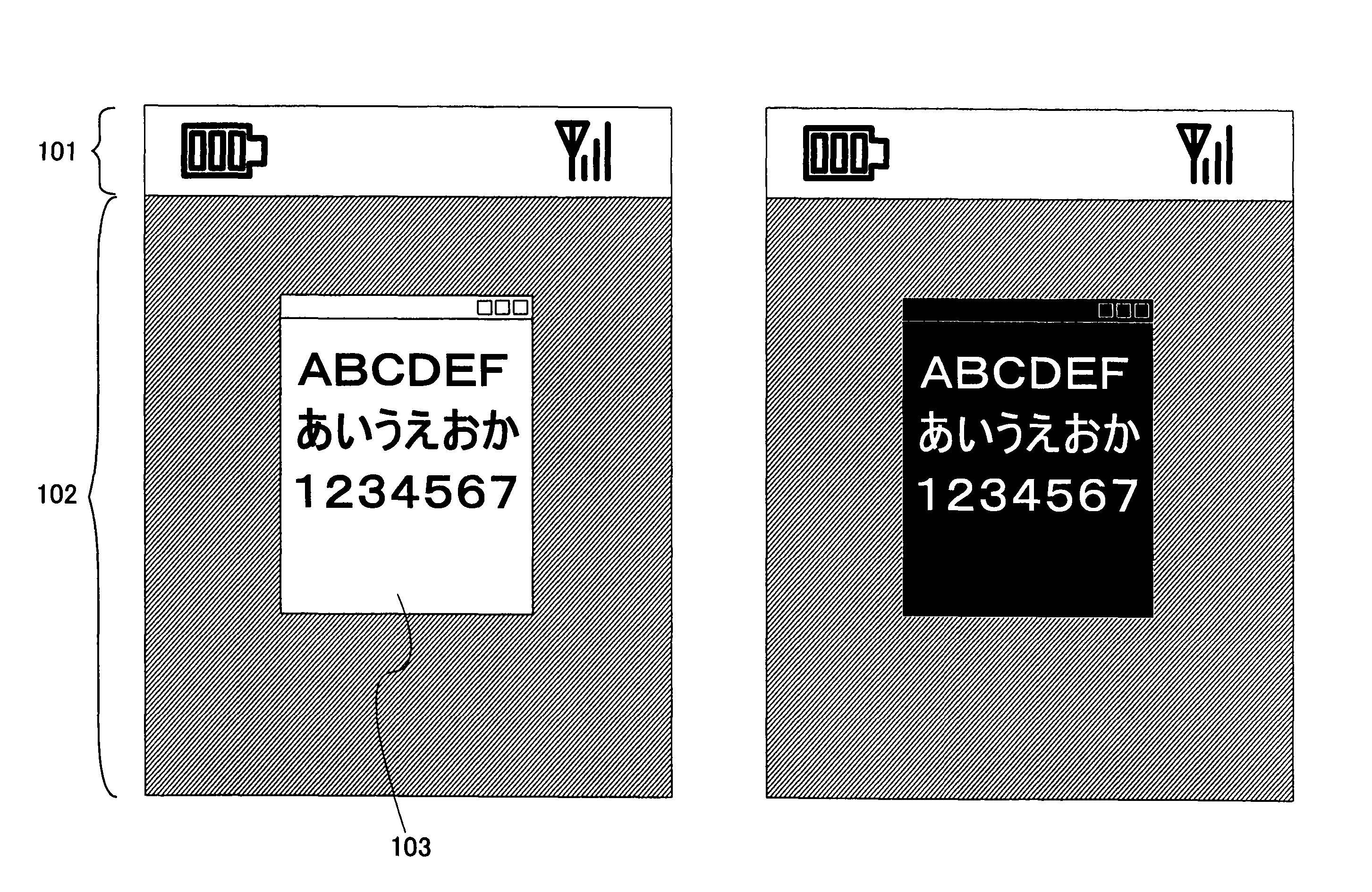
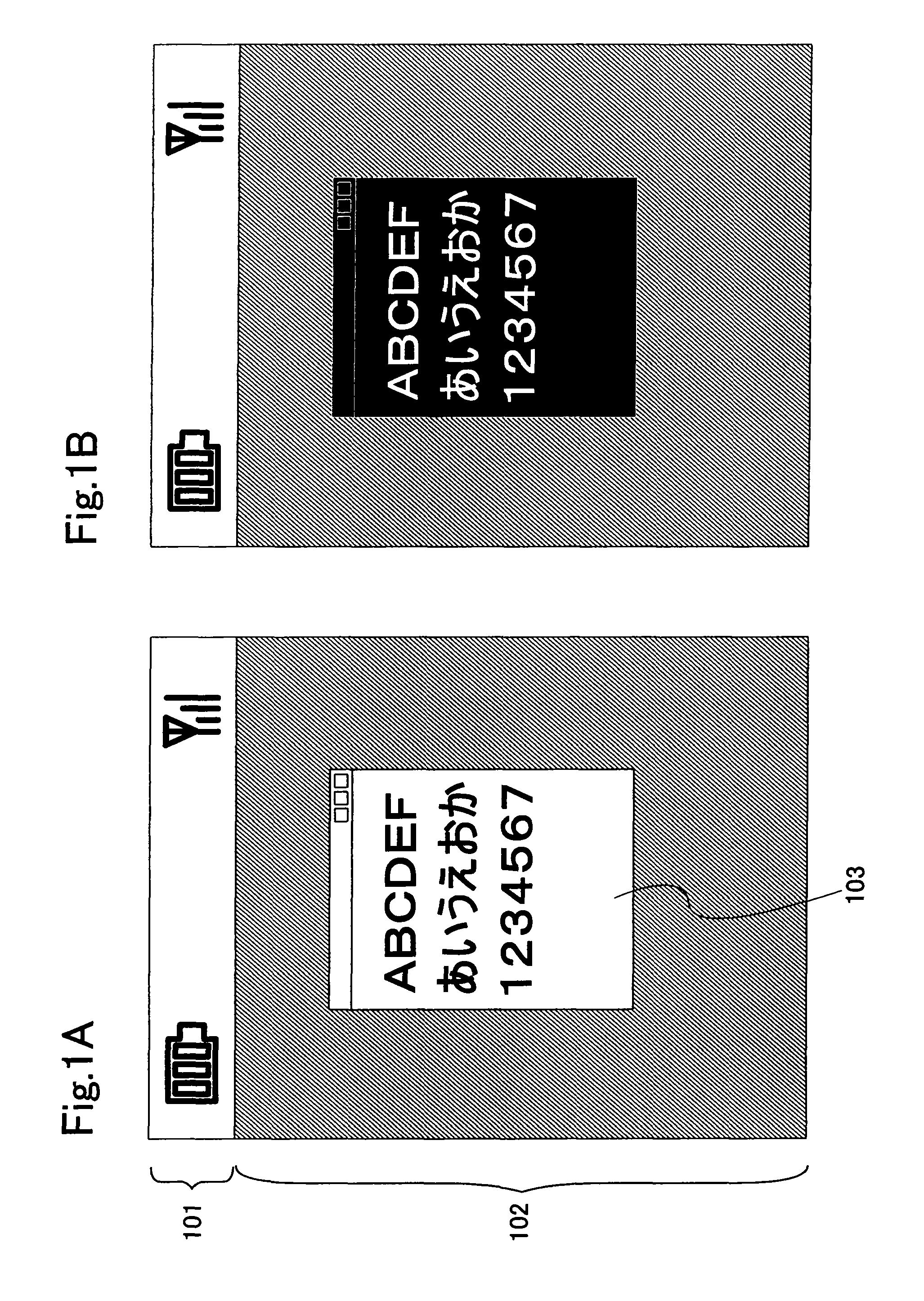
[0158] In this embodiment mode, a condition is set, and a gray scale of a displayed image is inverted when the condition is fulfilled. That is, a contrasting of a display image is inverted. The difference in deterioration of display elements in pixels is reduced, thereby suppressing variations in luminance of pixels.
[0159] For example, in the case where a gray scale is inverted in a display device for displaying 64 gray scales, pixels emitting light with gray scale levels of 0, 1, 2, 3, . . . , 62, and 63 before gray scale inversion are set so as to emit light with gray scale levels of 63, 62, 61, 60, . . . , 1, and 0. That is to say, when a display device for displaying N gray scales has a gray scale level of X before gray scale inversion and a gray scale level of Y after gray scale inversion, Y=N−X is satisfied.
[0160] Further, in the case where text (such as hiragana, katakana, kanji character, numerical character, or the Roman alphabet) is displayed in a display screen, switchi...
embodiment mode 2
[0174] In this embodiment mode, in the case where text (such as hiragana, katakana, kanji character, numerical character, or the Roman alphabet) is displayed in a display screen, a condition is set and switching between a black text mode where text is displayed in black and a black-rimmed white text mode where a core of text is displayed in white and an outline thereof is displayed in black is carried out each time the set condition is fulfilled. Alternatively, switching between a white text mode where text is displayed in white and a white-rimmed black text mode where a core of text is displayed in black and an outline thereof is displayed in white is carried out. FIG. 4A shows “one kana character” as an example of the black-rimmed white text mode. FIG. 4B shows “one kana character” as an example of the white-rimmed black text mode.
[0175] By switching between the modes in this manner, the difference in deterioration of display elements in pixels can be reduced. This is because tex...
embodiment mode 3
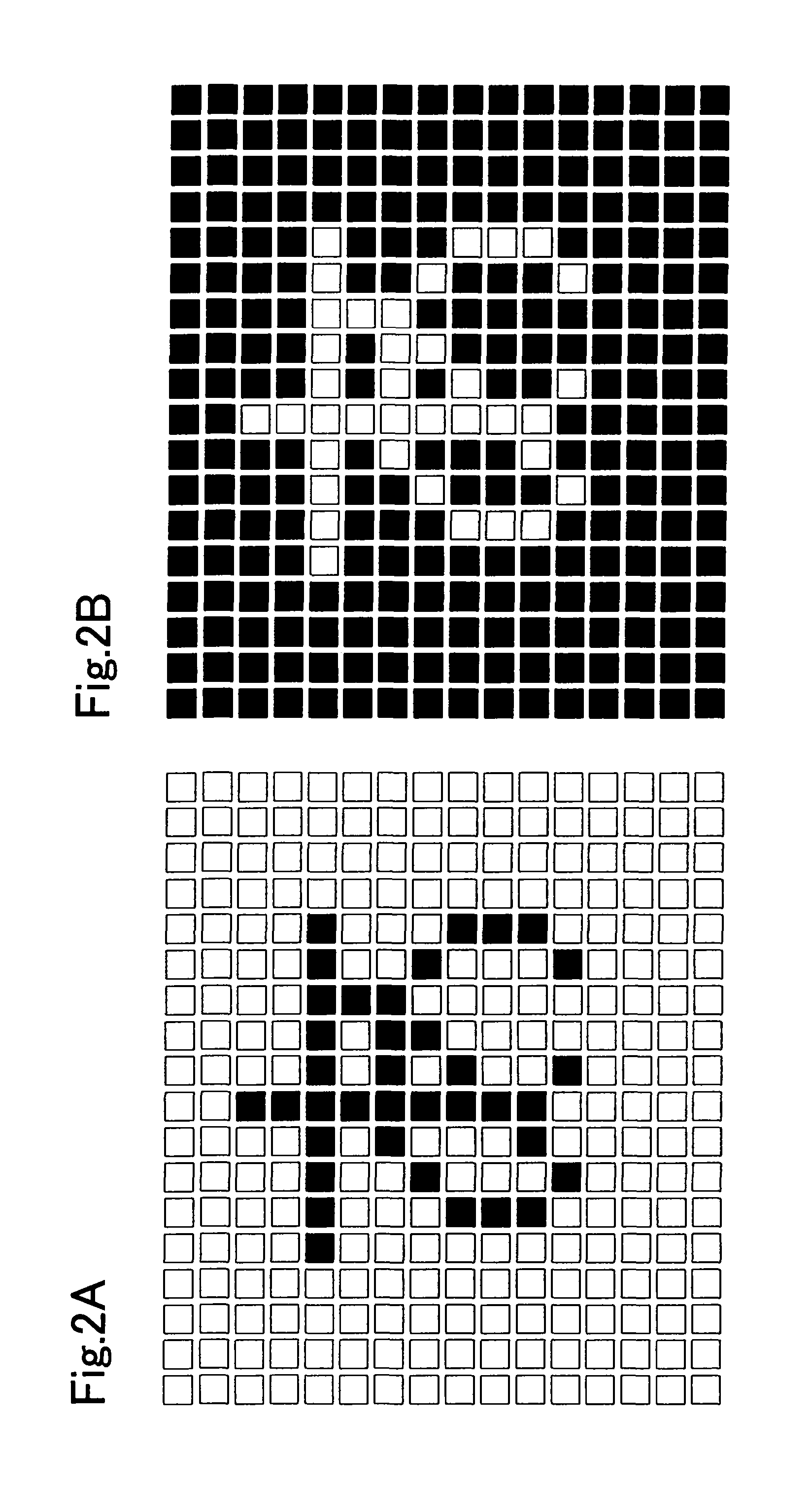
[0178] In this embodiment mode, an image burn-in phenomenon is suppressed by shifting an image. This is particularly effective in the case where a displayed image is text (such as hiragana, katakana, kanji character, numerical character, or the Roman alphabet) or the like, which has a definite boundary of gradations.
[0179]FIG. 5 shows a diagram in the case where a character “one kana character” is shifted by one pixel in the right direction and the down direction. The character “one kana character” before shifted is indicated by shaded pixels, and the character “one kana character” after shifted is indicated by black pixels. As an example, a text block for forming one character corresponds to pixels arranged so as to have a rectangular shape with 7×7 pixels. Note that the text block corresponds to a collection of the smallest rectangular pixels which can display any kind of character which has the same font type and size. The character “one kana character” before shifted is formed ...
PUM
 Abstract
Description
Claims
Application Information
 - R&D
- Intellectual Property
- Life Sciences
- Materials
- Tech Scout
- Unparalleled Data Quality
- Higher Quality Content
- 60% Fewer Hallucinations
Browse by: Latest US Patents, China's latest patents, Technical Efficacy Thesaurus, Application Domain, Technology Topic, Popular Technical Reports.
© 2025 PatSnap. All rights reserved.Legal|Privacy policy|Modern Slavery Act Transparency Statement|Sitemap|About US| Contact US: help@patsnap.com


