Apparatus for securing siding

a technology for fixing screws and siding, applied in the direction of threaded fasteners, screws, fastening means, etc., can solve the problems of clogging the thread grooves of the slot edges, the need for vinyl to be able to expand and contract,

Inactive Publication Date: 2007-07-19
HARNEY DONALD
View PDF5 Cites 3 Cited by
  • Summary
  • Abstract
  • Description
  • Claims
  • Application Information

AI Technical Summary

Problems solved by technology

A problem exists in that the vinyl must be able to expand and contract to avoid bubbling or twisting.
Because the self-tapping screw has threads that extend the length of the shaft, the edges of the slot become stuck in the grooves of the threads.

Method used


Image

  • Apparatus for securing siding
  • Apparatus for securing siding
  • Apparatus for securing siding

Examples


Embodiment Construction

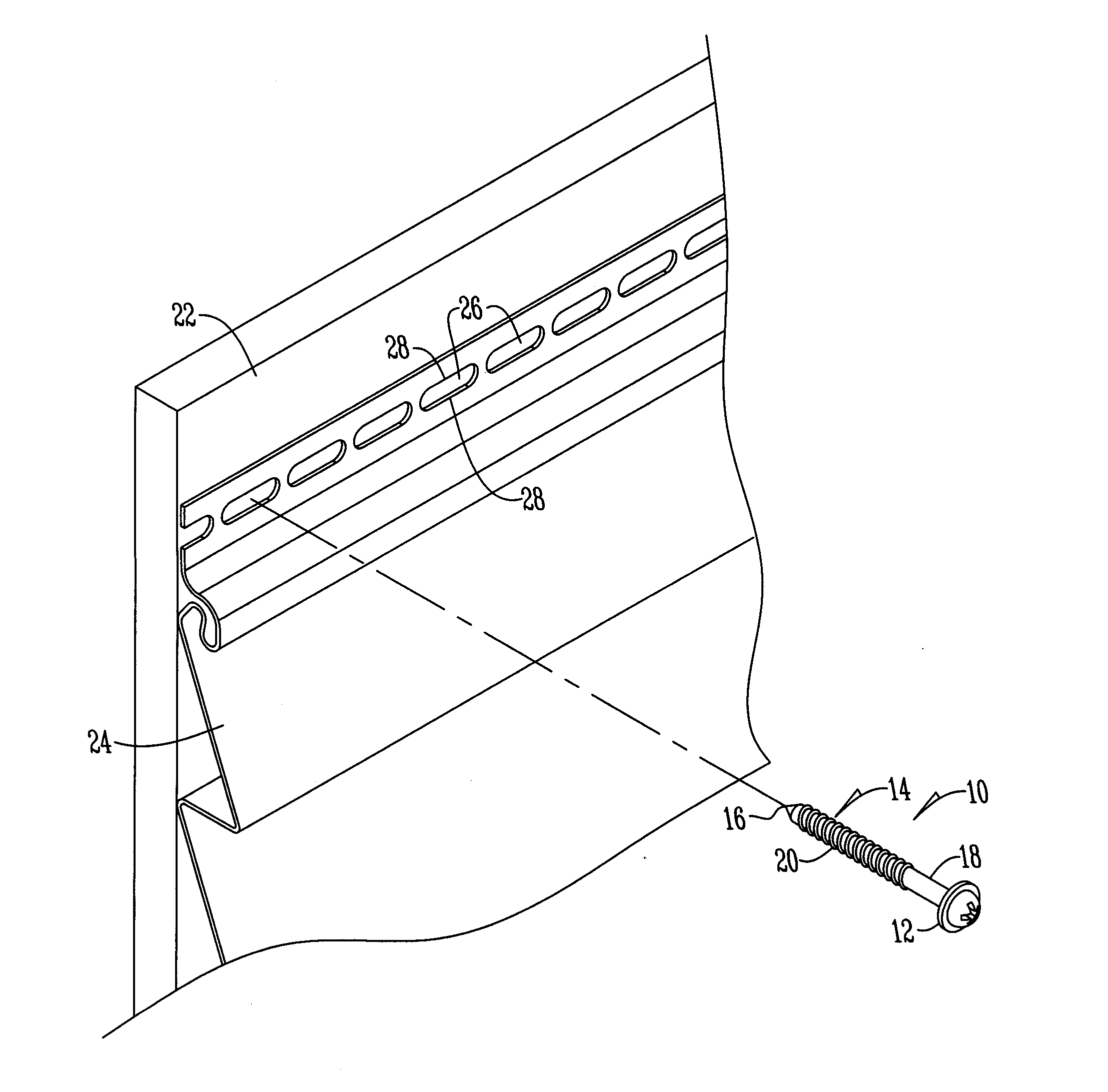
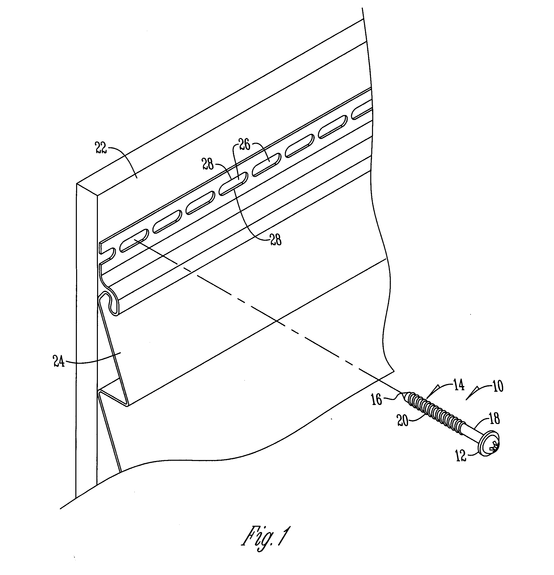
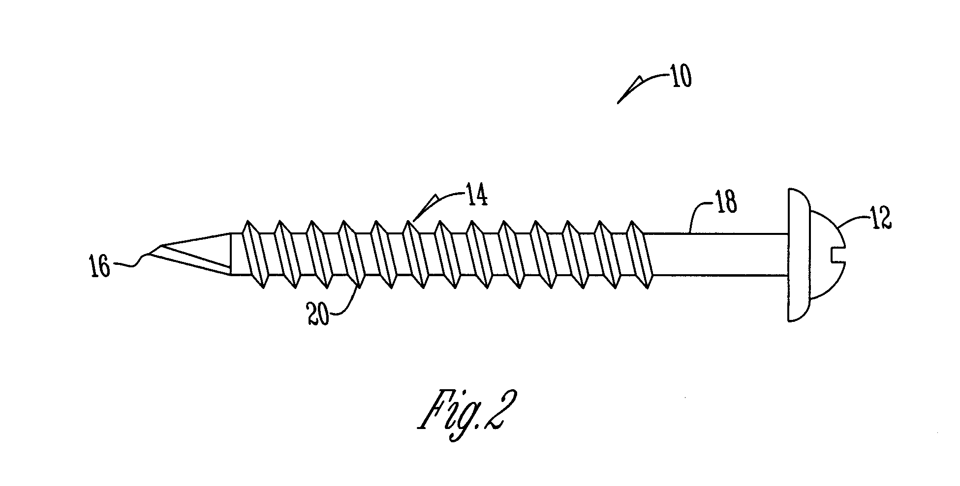
[0008] Referring to the Figures, a screw 10 has a head 12. Preferably, the head 12 is formed similar to a pan head, wafer, “s”, truss head, or washer head screw. Also preferred is a head having at least a ⅜″ (9.5 mm) diameter.

[0009] Extending from the head 12 is a shaft 14 that terminates in a tip 16. The tip 16 is of different types such as a drill point, sharp point, or the like. Optimally, the shaft has at least a ⅛″ (3 mm) diameter and at least a length of 1⅛″ (29 mm). The shaft has a first or substantially smooth portion 18 and a second or threaded portion 20 that extends outwardly from the smooth portion toward the tip 16. Optimally, the smooth portion 18 extends ½″ from the head 12.

[0010] While the screw may be used to apply the siding to a variety of surfaces, one example includes applying siding over metal studs. To begin a wall sheathing 22 is installed over the studs to provide a straighter, smoother, more rigid wall surface to help prevent the studs from twisting. The ...


PUM


Abstract

An apparatus for securing vinyl siding to a surface having a head and a shaft that extends outwardly from the head and terminates in a tip. The shaft has a substantially smooth portion adjacent the head and a threaded portion that extends from the smooth portion toward the tip. The smooth portion is received within a slot in the vinyl such that the vinyl may slide longitudinally along the length of the slot in relation to the screw.

Description

BACKGROUND OF THE INVENTION [0001] This invention is directed toward an apparatus for securing siding, and more particularly to a screw for securing siding over a steel stud. [0002] Vinyl siding is known in the art and has a plurality of slots through which a plurality of fastening devices such as nails and screws are inserted through the slots to secure the siding to the mounting surface. To apply the siding over a steel stud generally a non-corrosive self-tapping screw is inserted through the slot of the vinyl and screwed into a wall sheathing that is installed over the studs. A problem exists in that the vinyl must be able to expand and contract to avoid bubbling or twisting. Because the self-tapping screw has threads that extend the length of the shaft, the edges of the slot become stuck in the grooves of the threads. As a result, the siding will not slide in relation to the screw. This is particularly the case with a fold that has a pair of slots in spaced alignment. Therefore,...

Claims


Application Information

Patent Timeline
Patent Type & Authority Applications(United States)
IPC IPC(8): F16B23/00F16B35/06
CPCF16B25/0031
Inventor HARNEY, DONALD
Owner HARNEY DONALD
Why Eureka
Try Eureka