Universal serial bus connecting device
- Summary
- Abstract
- Description
- Claims
- Application Information
AI Technical Summary
Benefits of technology
Problems solved by technology
Method used
Image

Examples
first embodiment
The First Embodiment
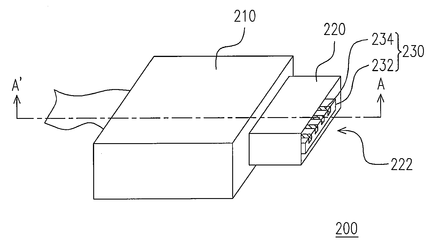
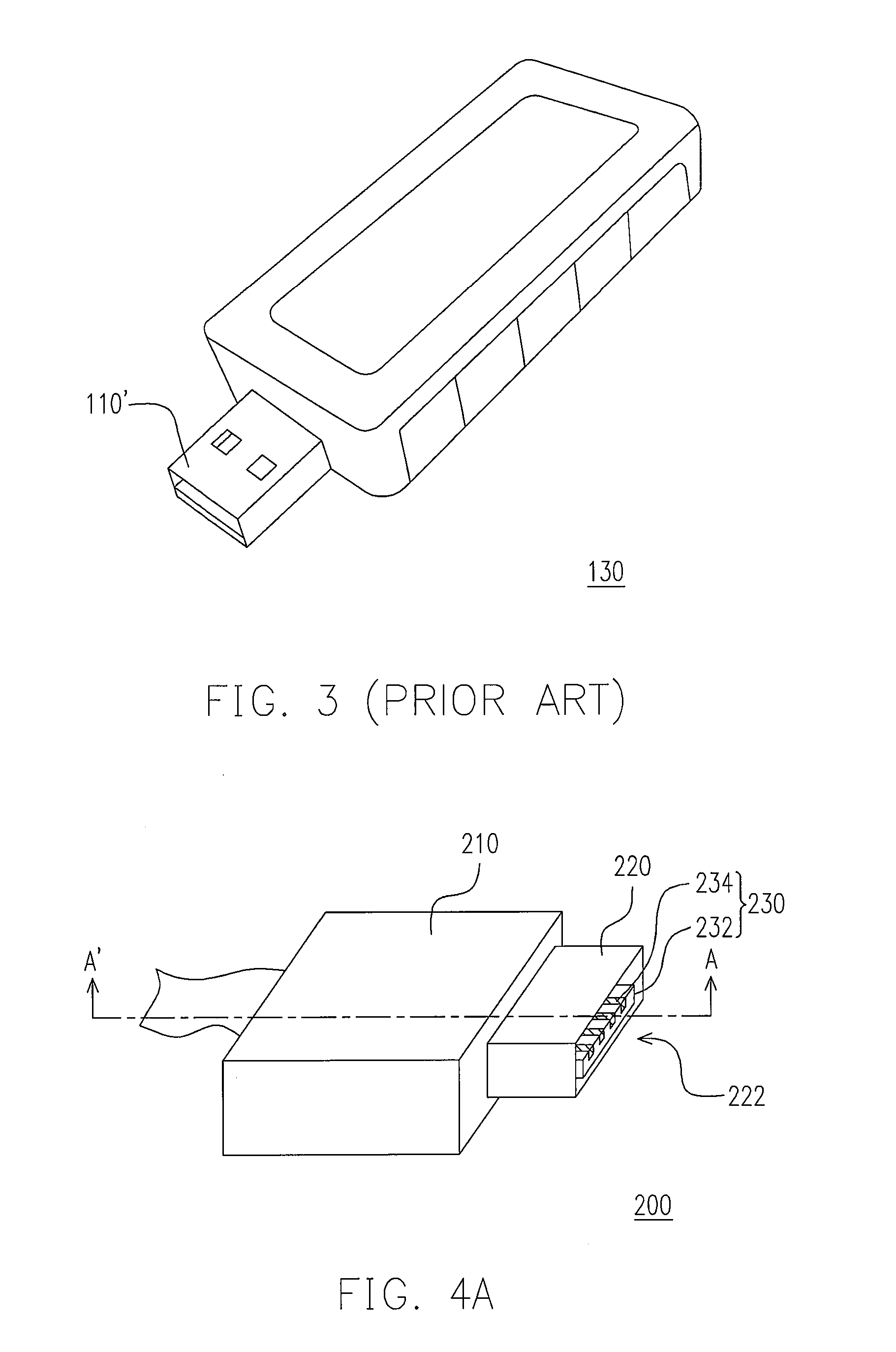
[0041]FIG. 4A is a schematic view of the USB connecting device according to a first embodiment of the present invention. FIG. 4B is a cross-sectional view of FIG. 4A along the line A-A′. Referring to FIGS. 4A and 4B, the USB connecting device 200 of this embodiment is a USB transmission line, which includes a first housing 210, a second housing 220, a connector 230, and four second pins 240. The second housing 220 is disposed at one side of the first housing 210, and has a first opening 222 being located at one side of the second housing 220 far from the first housing 210. The connector 230 includes a substrate 232 movably inserted in the second housing 220, and four first pins 234 embedded in the substrate 232. The first pins 234 are disposed at one end of the substrate 232 adjacent to the first opening 222. Moreover, the four second pins 240 are disposed within the second housing 220 and connected to the transmission line via a connecting line 241. Each second ...
second embodiment
The Second Embodiment
[0048]FIG. 5A is a cross-sectional view of the USB connecting device used as a receptacle according to a second embodiment of the present invention. In this embodiment and the first embodiment of the present invention, identical or similar reference numerals refer to identical or similar elements, which thus the description of those is omitted here.
[0049]Referring to FIGS. 4B and 5A, the difference between the first and second embodiments lies in that: the second housing 220 of the first embodiment is fixed on one side of the first housing 210, and in the first embodiment, the relative position between the connector 230 and the second housing 220 is changed by moving the connector 230, so as to make the USB connecting device 200 form a plug or a receptacle. The connector 230′ of the USB connecting device 200′ in this embodiment is fixed within the first housing 210. The second housing 220′ is movably disposed at one side of the first housing 210. And the first p...
third embodiment
The Third Embodiment
[0053]FIG. 6A is a cross-sectional view of the USB connecting device used as a receptacle according to a third embodiment of the present invention. Different from that of the first and second embodiments, the USB connecting device 300 of this embodiment is applied to an electronic device, such as a flash drive or a portable MP3 player.
[0054]Referring to FIG. 6A, the USB connecting device 300 of this embodiment includes a first housing 310, a second housing 320, a connector 330, four second pins 340, and a circuit board 370. The second housing 320 of this embodiment is fixed on lo one side of the first housing 310, and a first opening 322 is disposed at one side of the second housing 320 far from the first housing 310. In another embodiment, the second housing 320 also can be integrated with the first housing 310, as shown inFIG. 6C.
[0055]In view of the above, the connector 330 includes a substrate 332 movably inserted in the second housing 320, and four first pin...
PUM
 Abstract
Description
Claims
Application Information
 - R&D Engineer
- R&D Manager
- IP Professional
- Industry Leading Data Capabilities
- Powerful AI technology
- Patent DNA Extraction
Browse by: Latest US Patents, China's latest patents, Technical Efficacy Thesaurus, Application Domain, Technology Topic.
© 2024 PatSnap. All rights reserved.Legal|Privacy policy|Modern Slavery Act Transparency Statement|Sitemap