Inflatable temporary door

a temporary door and inflatable technology, applied in the direction of door/window protective devices, curtain rods, applications, etc., can solve the problem of bugs flying into the hom

Inactive Publication Date: 2007-08-09
EARNEST TODD
View PDF7 Cites 35 Cited by
  • Summary
  • Abstract
  • Description
  • Claims
  • Application Information

AI Technical Summary

Problems solved by technology

This can be problematic in that during the spring and summer time bugs fly into a home which is undesirable.
Additionally, when construction or vacuuming is done during construction dust and debris in a room filters into the rest of a home.

Method used


Image

  • Inflatable temporary door
  • Inflatable temporary door
  • Inflatable temporary door

Examples


Embodiment Construction

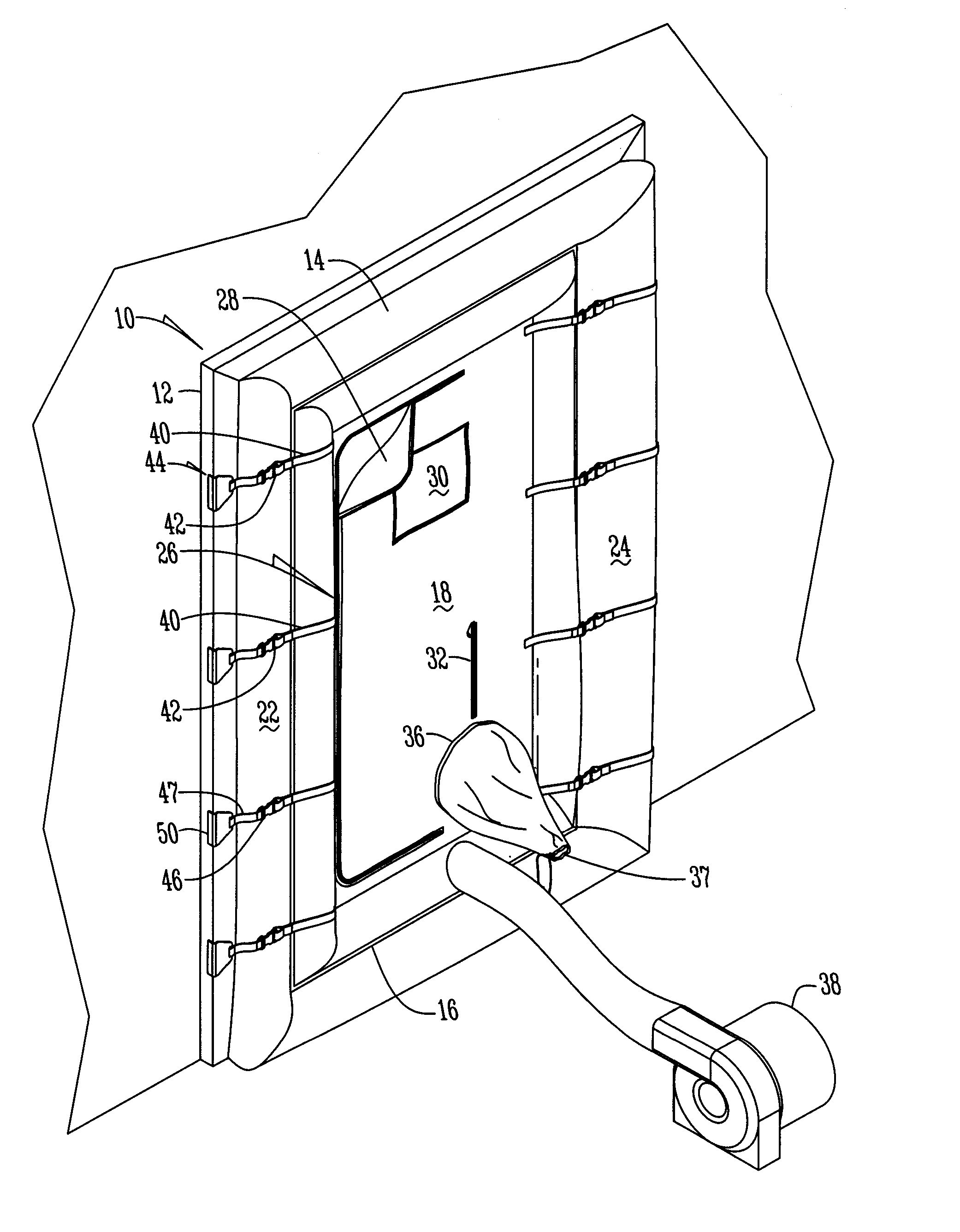
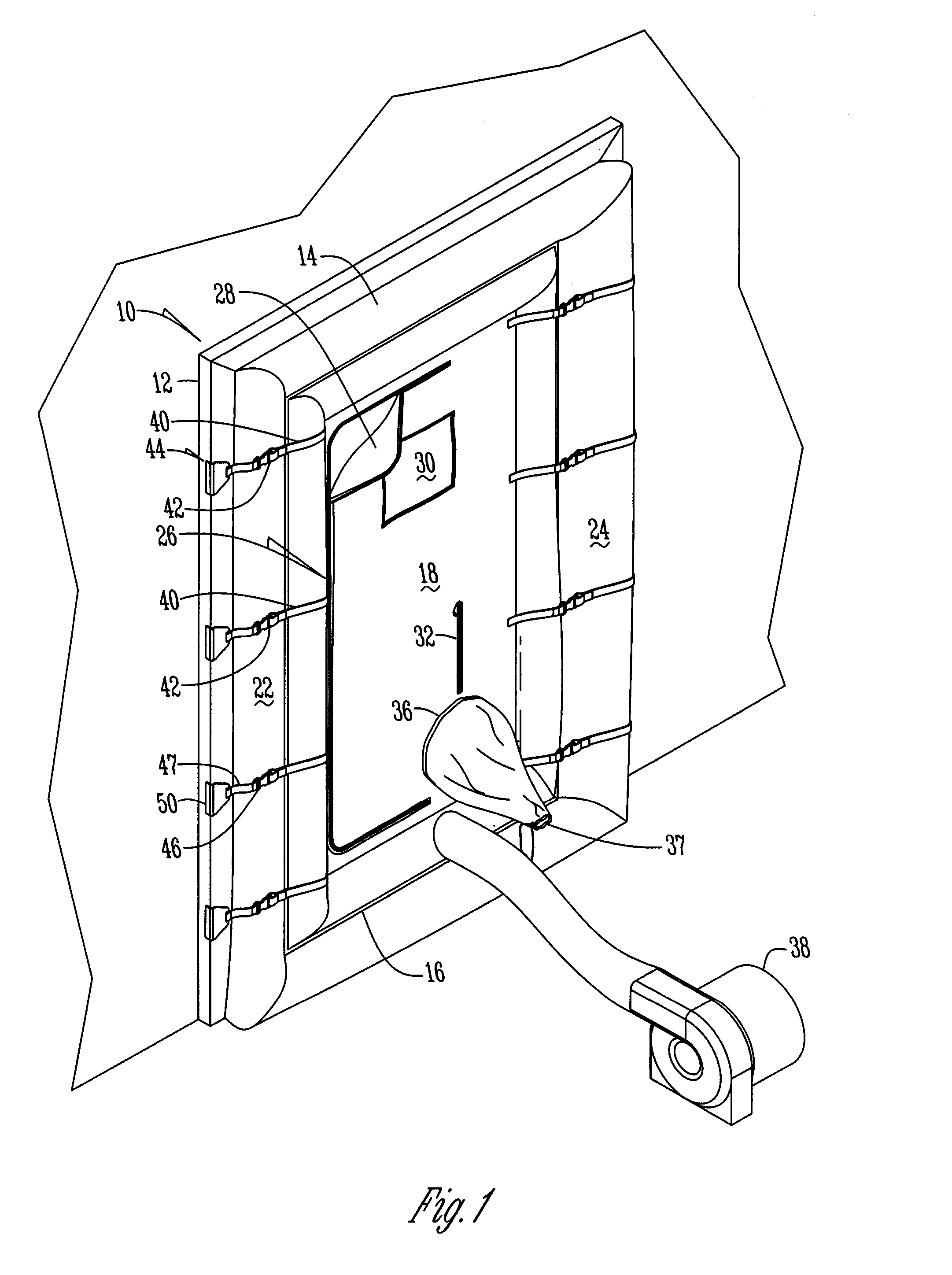
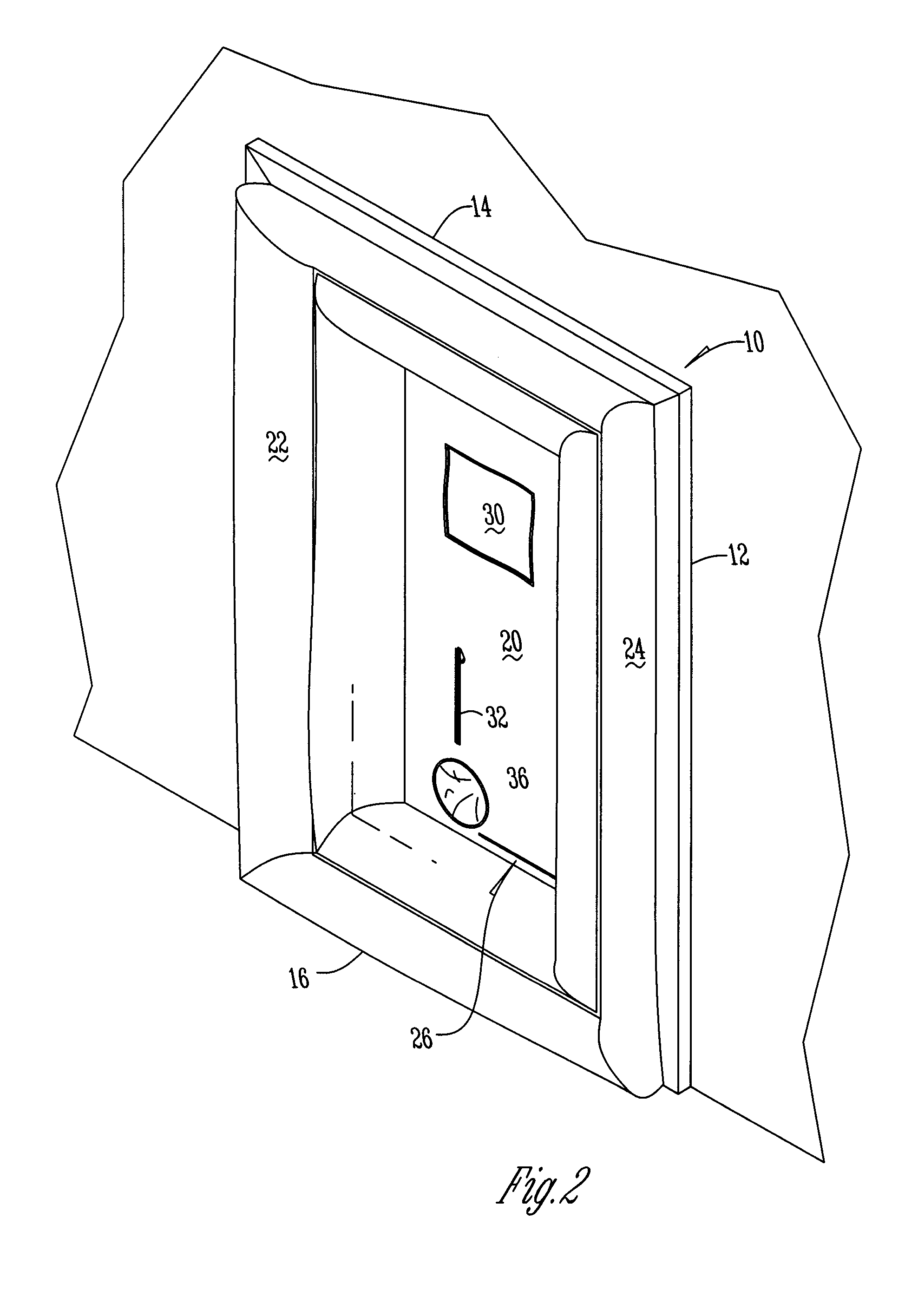
[0010]FIG. 1 shows an inflatable temporary door 10 within a door frame 12 of a wall or home. The inflatable temporary door 10 is made of material that will inflate to provide a seal within the door frame 12. In a preferred embodiment the inflatable temporary door, or inflated body 10 is generally rectangularly shaped and has a top 14, bottom 16, front 18, back 20 (FIG. 2), and first and second sides 22, 24.

[0011] The inflatable temporary door 10 additionally has an opening or retractable doorway 26 that extends from adjacent the top 14 of the door 10 to adjacent the bottom 16 of the door 10. In a preferred embodiment the doorway 26 is defined by a C-shaped zipper that when unzipped creates a retractable flap 28 that is pulled back to expose the doorway 26. In additional embodiments other types of fastening devices such as a snap fit, Velcro, or the like is used to create the retractable doorway so that an individual can pass through the door frame 12 without deflating the inflatabl...


PUM


Abstract

An inflatable temporary door for sealing the opening of a door frame. The inflatable door has a plurality of openings therein such that power cords, vacuum hoses, or the like are disposed through the inflatable door for use on the opposite side of the door frame. Additionally, the inflatable door has a C-shaped opening so that a person may enter or exit the door without removing the inflatable door. The inflatable door also has a plurality of straps that releasably attach to a bracket that is frictionally engaged to a doorframe to secure he inflatable door within the doorframe.

Description

BACKGROUND OF THE INVENTION [0001] This invention relates to an inflatable temporary door that is placed in a door frame when a doorway is being used to run electrical wires or hoses therethrough. Specifically, when workers clean ducts or do other work that requires heavy duty electrical outlets provided by an outside source the wires and hoses are run through the front door or window of a home so that the vacuum for the ducts or other electrical devices may be used indoors. Similarly, during construction projects when power tools are used, power cords are run out of a room for connection to a power source. By running the cords and hoses through the opening of a door or window the door or window is kept open during the time of use. This can be problematic in that during the spring and summer time bugs fly into a home which is undesirable. Additionally, when construction or vacuuming is done during construction dust and debris in a room filters into the rest of a home. Also, when a d...

Claims


Application Information

Patent Timeline
Patent Type & Authority Applications(United States)
IPC IPC(8): E06B9/00
CPCE04G21/24E06B9/00E06B7/32E06B5/025E04G21/241
Inventor EARNEST, TODD
Owner EARNEST TODD
Why Eureka
Try Eureka