Bicycle shifter

a shifter and bicycle technology, applied in the direction of steering devices, linear shafts, shafts, etc., can solve the problems of troublesome position alignment and difficult operation of shifters, and achieve the effect of convenient attachment to bicycles

Active Publication Date: 2007-08-30
SHIMANO INC
View PDF6 Cites 75 Cited by
  • Summary
  • Abstract
  • Description
  • Claims
  • Application Information

AI Technical Summary

Benefits of technology

[0010]One object of the present invention is to provide a bicycle shifter that can be easily attached to the bicycle in an adjustable manner.

Problems solved by technology

If the shifter is attached to the handlebar within the brake lever, then the shifter may be difficult to operate, depending on the shapes of the operating member(s) of the shifter.
Since the alignment of the main shifter body also changes when the attachment position of the main shifter body is varied, the alignment of the main shifter body must be adjusted, and such position alignment is troublesome.

Method used


Image

  • Bicycle shifter
  • Bicycle shifter
  • Bicycle shifter

Examples


second embodiment

[0050]Referring now to FIGS. 8 and 9, a shifter in accordance with a second embodiment will now be explained. In view of the similarity between the first and second embodiments, the parts of the second embodiment that are identical to the parts of the first embodiment will be given the same reference numerals as the parts of the first embodiment. Moreover, the descriptions of the parts of the second embodiment that are identical to the parts of the first embodiment may be omitted for the sake of brevity.

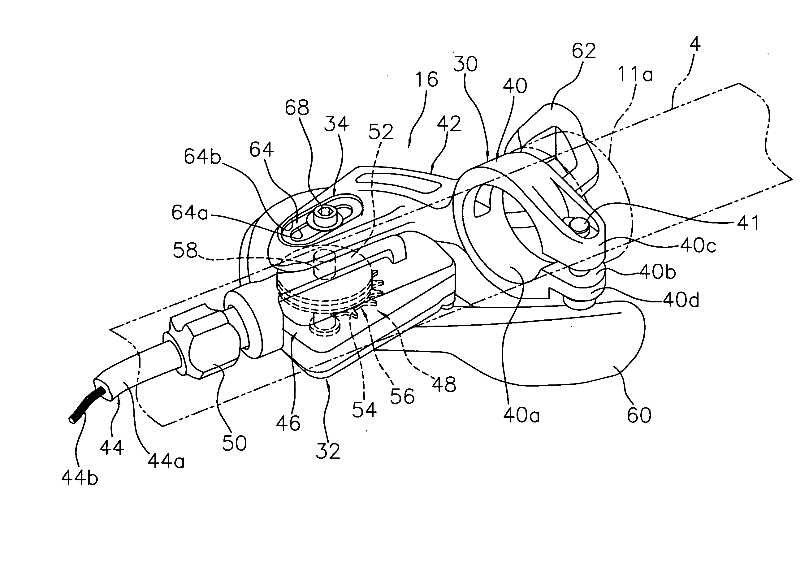
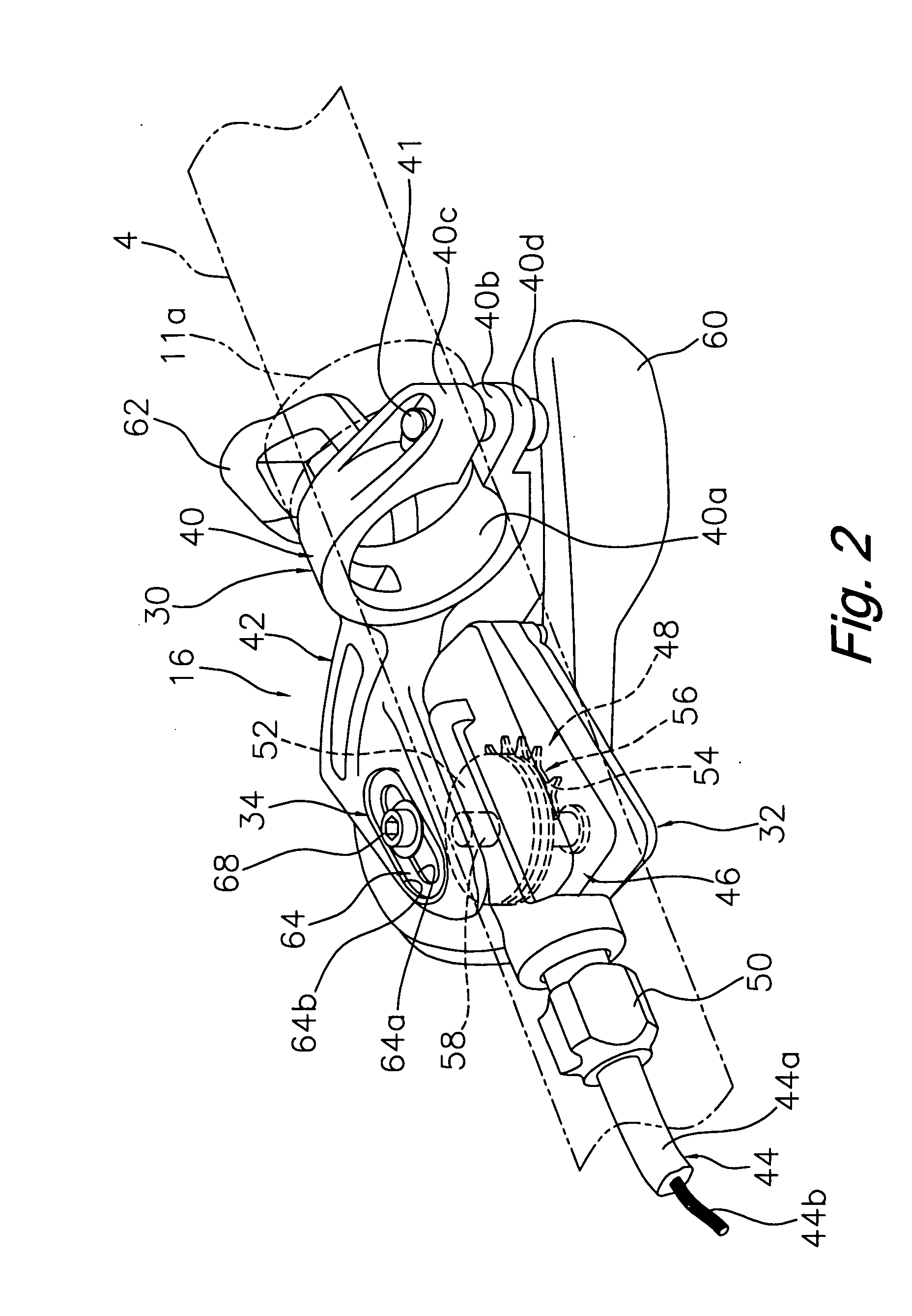
[0051]In a second embodiment, a fixing mechanism 134 is provided with a loosening-prevention member 178 that links the mounting bracket 30 to the main shifter body 32 in order to prevent a main shifter body 132 from coming loose when a bolt 168 is removed, as shown in FIGS. 8 and 9.

[0052]The fixing mechanism 134 basically includes the slot 64 of the mounting bracket 30 (discussed above), a loosening-prevention member 178 with a female threaded part 166, and a bolt 168 that is screwed...

third embodiment

Modification of Third Embodiment

[0058]Referring now to FIGS. 11 and 12, a modification to the shifter of the third embodiment will now be explained. In view of the similarity between the modification of the third embodiment and the prior embodiments, the parts of the modification of the third embodiment that are identical to the parts of the prior embodiments will be given the same reference numerals as the parts of the prior embodiments. Moreover, the descriptions of the parts of the modification of the third embodiment that are identical to the parts of the prior embodiments may be omitted for the sake of brevity.

[0059]In FIGS. 11 and 12, a loosening-prevention member 378 of a fixing mechanism 334 is cylindrical and has oval-shaped flanges 378a and 378b at either end. The housing 46 and the mounting bracket 30 can be coupled and released by rotating the loosening-prevention member 378 by 90 degrees between an inserted position (solid lines in FIG. 11) at which the member is insert...

fourth embodiment

[0061]Referring now to FIG. 13, a shifter in accordance with a fourth embodiment will now be explained. In view of the similarity between the fourth embodiment and the prior embodiments, the parts of the fourth embodiment that are identical to the parts of the prior embodiments will be given the same reference numerals as the parts of the prior embodiments. Moreover, the descriptions of the parts of the fourth embodiment that are identical to the parts of the prior embodiments may be omitted for the sake of brevity.

[0062]The shifter in accordance with this fourth embodiment includes the shifter mechanism 48 of the first embodiment with the winding body 52 and the positioning member 54 of the positioning mechanism 56. However, the positioning member 54 for positioning the winding body 52 are supported by the shaft member 158 of the third embodiment shown in FIG. 12. In the previous embodiments, a slot was formed in the mounting bracket 30 in the fixing mechanism. However, another pos...


PUM


Abstract

A bicycle shifter is configured to ensure that the position where a main shifter body is attached to a bicycle can be easily varied. The bicycle shifter basically has a mounting bracket, a main shifter body and a fixing mechanism. The mounting bracket is preferably configured be fixed to a handlebar of a bicycle. The main shifter body is mounted on the mounting bracket and has a shifter mechanism in the interior. The fixing mechanism is a mechanism whereby the main shifter body can be fixed in place on the mounting bracket at an arbitrary attachment position between a first position and a second position.

Description

CROSS-REFERENCE TO RELATED APPLICATIONS[0001]This application claims priority under 35 U.S.C. § 119 to Japanese Patent Application No. 2006-039620 on Feb. 16, 2006. The entire disclosure of Japanese Patent Application No. 2006-039620 is hereby incorporated herein by reference.BACKGROUND OF THE INVENTION[0002]1. Field of the Invention[0003]This invention generally relates to a bicycle shifter. More specifically, the present invention relates to a bicycle shifter that is mounted on a bicycle and that is used to shift the gears of a bicycle.[0004]2. Background Information[0005]Bicycling is becoming an increasingly more popular form of recreation as well as a means of transportation. Moreover, bicycling has become a very popular competitive sport for both amateurs and professionals. Whether the bicycle is used for recreation, transportation or competition, the bicycle industry is constantly improving the various components of the bicycle. One component that has been extensively redesign...

Claims


Application Information

Patent Timeline
Patent Type & Authority Applications(United States)
IPC IPC(8): F16C1/10
CPCB62K23/06B62M25/04Y10T74/20822Y10T74/20287Y10T74/20438
Inventor KAWAKAMI, TATSUYAFUNAI, SHINGO
Owner SHIMANO INC
Why Eureka
Try Eureka