Cap assembly for bottles

a bottle and cap assembly technology, applied in the field of bottle cap assembly, can solve the problems of water leakage from the gap, easy contamination of the cap member b,

Inactive Publication Date: 2007-08-30
HUNG MING HUA
View PDF9 Cites 69 Cited by
  • Summary
  • Abstract
  • Description
  • Claims
  • Application Information

AI Technical Summary

Benefits of technology

[0009] In accordance with an aspect of the present invention, there is provided a cap assembly that includes a base member threadedly connected to a bottle and having a tube extending from a top thereof and a rod located at a center of the tube. A top flange extends radially outward from a top end of the tube. A plurality of connection ribs are connected between the rod and a bottom of the tube. A plurality of apertures are defined between the connection ribs. A cap member is movably mounted on the tube and includes an outer engaging tube and an inner engaging tube which shares a common axis with the outer engaging tube. A top plate is connected on two respective top ends of the outer engaging tube and the inner engaging tube. An outlet defined through the top plate and located corresponding to the rod so that when the inner engaging tube is inserted into an annular gap between the rod and an inner periphery of the tube, the rod movably seals the outlet. A lower end of the inner engaging tube is located corresponding to the apertures. A first flange extends from an inner periphery of the outer engaging tube and is stopped by the top flange to prevent the cap member from being disengaged from the tube when the cap member is moved upward.

Problems solved by technology

However, wearing between the inner engaging tube B2 and the tube A2 results a gap and the water leaks from the gap even when the rod A1 is engaged with the outlet B3.
Furthermore, the users have to hold and pull the cap member B so that the cap member B is easily contaminated.

Method used


Image

  • Cap assembly for bottles
  • Cap assembly for bottles
  • Cap assembly for bottles

Examples


Embodiment Construction

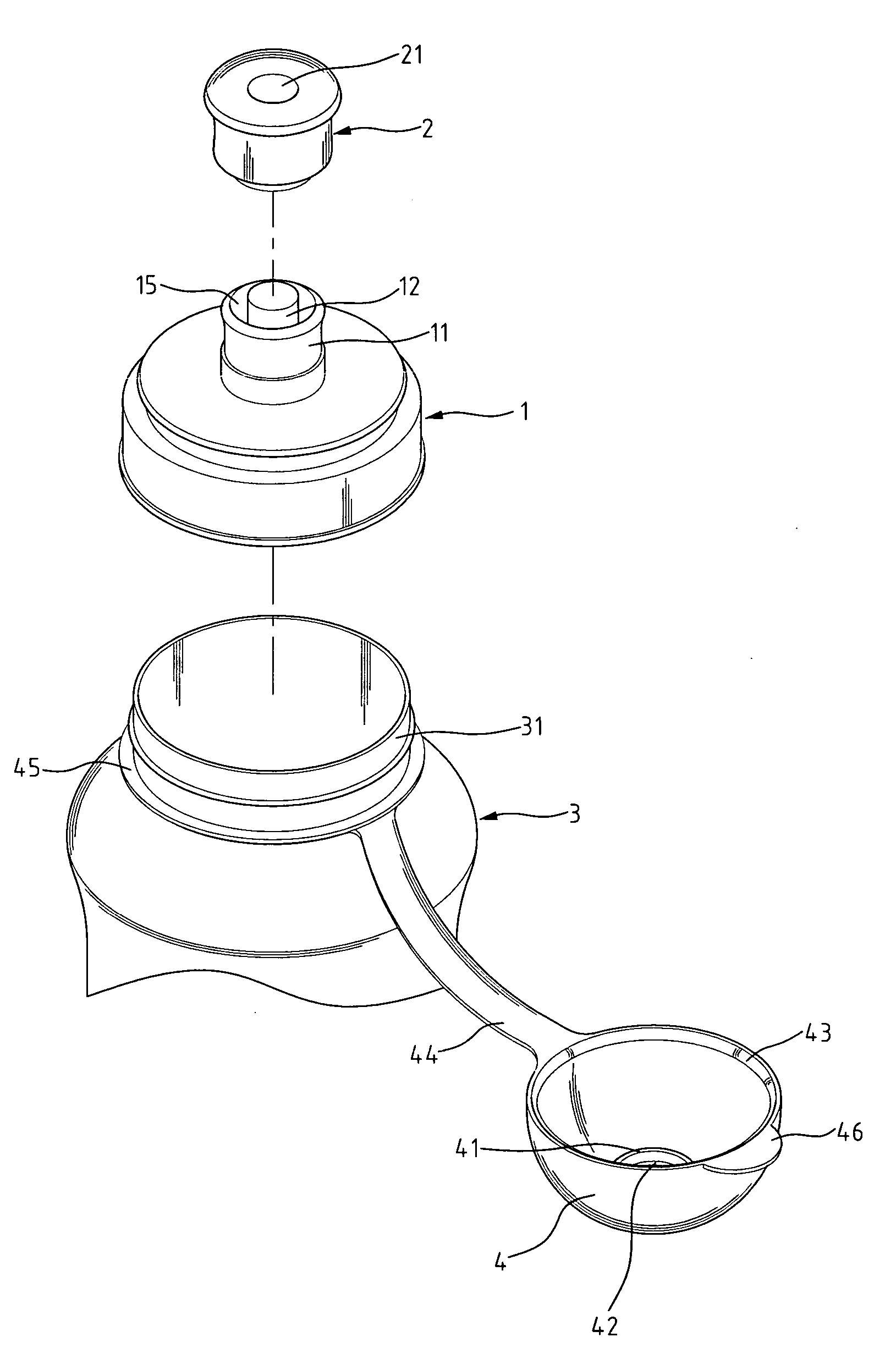
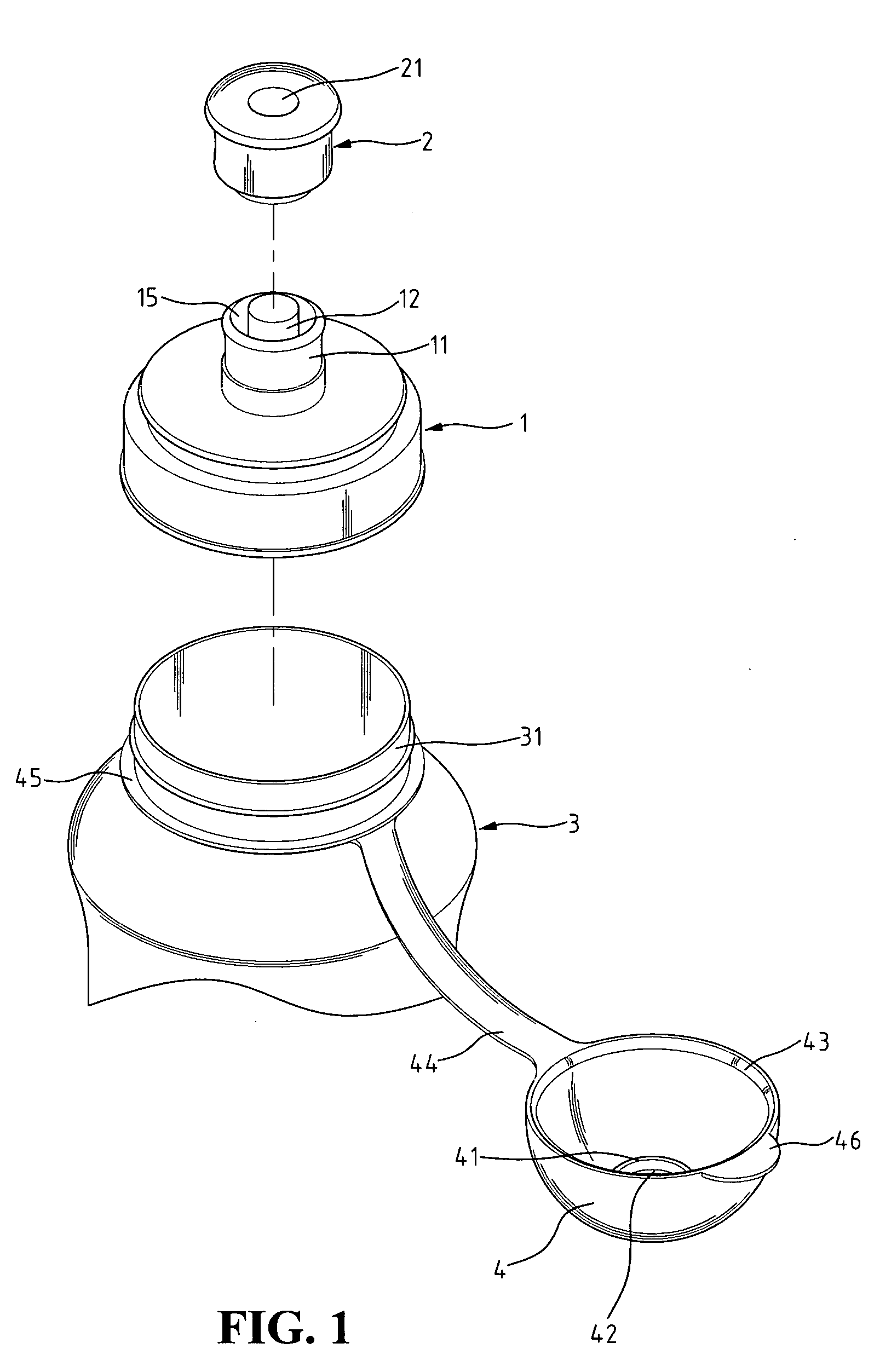
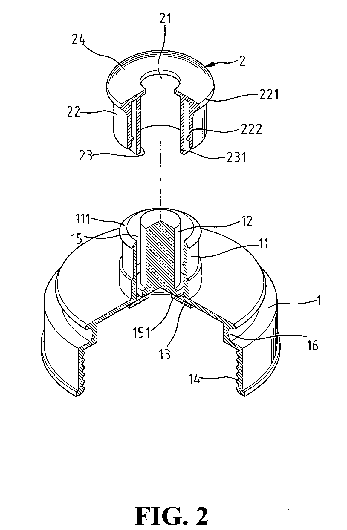
[0019] With reference to the drawings and in particular to FIGS. 1-5, a cap assembly in accordance with the present invention comprises a base member 1 which includes an inner threaded periphery 14 so as to be threadedly connected to an outer threaded periphery 31 of a bottle 3, a tube 11 extending from a top of the base member 1 and a rod 12 located at a center of the tube 11. The rod 12 can be a solid or a hollow rod. A plurality of connection ribs 13 are connected between the rod 12 and an bottom of the tube 11. An annular gap 15 is defined between the rod 12 and an inner periphery of the tube 11. A plurality of apertures 151 are defined between the connection ribs 13, and a top flange 111 extends radially outward from a top end of the tube 11. The top flange 111 has a triangular cross section.

[0020] A cap member 2 has an outer engaging tube 22 and an inner engaging tube 23, and the inner engaging tube 23 shares a common axis with the outer engaging tube 22. A top plate 24 is co...


PUM


Abstract

A cap assembly includes a base member having a tube and a rod. A cap member has an outer engaging tube and an inner engaging tube. A top plate is connected on two respective top ends of the outer engaging tube and the inner engaging tube. The inner engaging tube is inserted into an annular gap between the rod and an inner periphery of the tube and, the rod movably seals an outlet defined in the cap member. A first flange extends from an inner periphery of the outer engaging tube and is stopped by a top flange extending radially outward from a top end of the tube to prevent the cap member from being disengaged from the tube. A cover is mounted on the base member and is connected with the cap member so that users can simply open the cover to pull the cap member upward.

Description

BACKGROUND OF THE INVENTION [0001] 1. Field of the Invention [0002] The present invention relates to a cap assembly for bottles, which includes a cap member cooperated with a cover, so that a user does not need to touch the cap member to drink the contents in the bottles. [0003] 2. The Prior Arts [0004] Some bottled products such as water or sport drinks, are designed for outdoor use and the cap assembly does not need to be separated from the bottle when users drink the water or sport drinks. This purpose is achieved by using a valve connected to the cap assembly so that the users can have the water or sport drinks without removing a cap member from the bottles. [0005]FIGS. 7 and 8 show a conventional cap assembly that achieves the purpose mentioned above. The conventional cap assembly includes a base member “A” and a cap member “B”. A tube A2 extends from the base member A and a first flange A21 extends outward from an outer periphery of the tube A2. A plurality of connection ribs ...

Claims


Application Information

Patent Timeline
Patent Type & Authority Applications(United States)
IPC IPC(8): B65D51/16B65D55/16B65D83/00
CPCB65D47/243
Inventor HUNG, MING-HUA
Owner HUNG MING HUA
Why Eureka
Try Eureka