Method adn apparatus for turf aerifcation

a technology of aeration hole and aeration method, which is applied in the field of soil aerification, can solve the problems of increasing soil compaction around newly created aerification, tearing damage to the remaining grass, and low efficiency of the approach to reduce compaction, so as to achieve the effect of reducing the compaction of the surrounding earth and increasing the density of the aerification hol

Inactive Publication Date: 2007-09-20
FALTYSEK DANIEL R
View PDF20 Cites 9 Cited by
  • Summary
  • Abstract
  • Description
  • Claims
  • Application Information

AI Technical Summary

Benefits of technology

[0039] The method and apparatus of the present invention combines the speed and mechanical simplicity of solid or hollow tine aerification with the penetration depth, clean cutting and cylinder wall fracturing of deep drill aerification. A turf drill is held in a chuck which permits free rotation of the drill bit when it is pushed into the ground (loaded in compression) but which restricts rotation of the bit when it is withdrawn from the ground (loaded in tension). When the chuck is locked and the drill bit is pulled from the soil, the flutes on the bit cut a clean, generally cylindrical hole in the soil with minimal compaction of the surrounding earth. In one embodiment, the drill bit comprises a non-fluted upper portion which helps prevent entanglement and lifting of the turf as the bit is withdrawn.

Problems solved by technology

Drum-type roller aerators will work but may cause tearing damage to the remaining grass since this type of cutter enters the turf at one angle, moves in an arc with the drum movement, and is withdrawn at a different angle.
This actually increases soil compaction around newly created aerification holes.
While they do not relieve soil compaction as efficiently as hollow tine aerification, these practices cause less surface disruption and can be done anytime.
Using triangular blades ranging in size 100-250 mm (4″ to 10″), these machines create lots of short, narrow, close slits; slitting is useful for getting air down into the soil; it's quick; it does a fair job in dethatching; however, this approach is not highly effective at reducing compaction.
This new technology has not been commonly available for use outside of golf course applications.
Deep drill aerifiers are also preferred for use in all problem areas because the rotating drill bits will penetrate subsoil areas, where other machines tend to walk or bounce, often causing trauma to the playing surface.
However, drill aerification is a very slow process as compared to reciprocating type aerifiers.

Method used


Image

  • Method adn apparatus for turf aerifcation
  • Method adn apparatus for turf aerifcation
  • Method adn apparatus for turf aerifcation

Examples


Embodiment Construction

[0054] In the following description, “drill” should be understood to mean an apparatus comprising both a drill chuck and a drill bit held within the chuck.

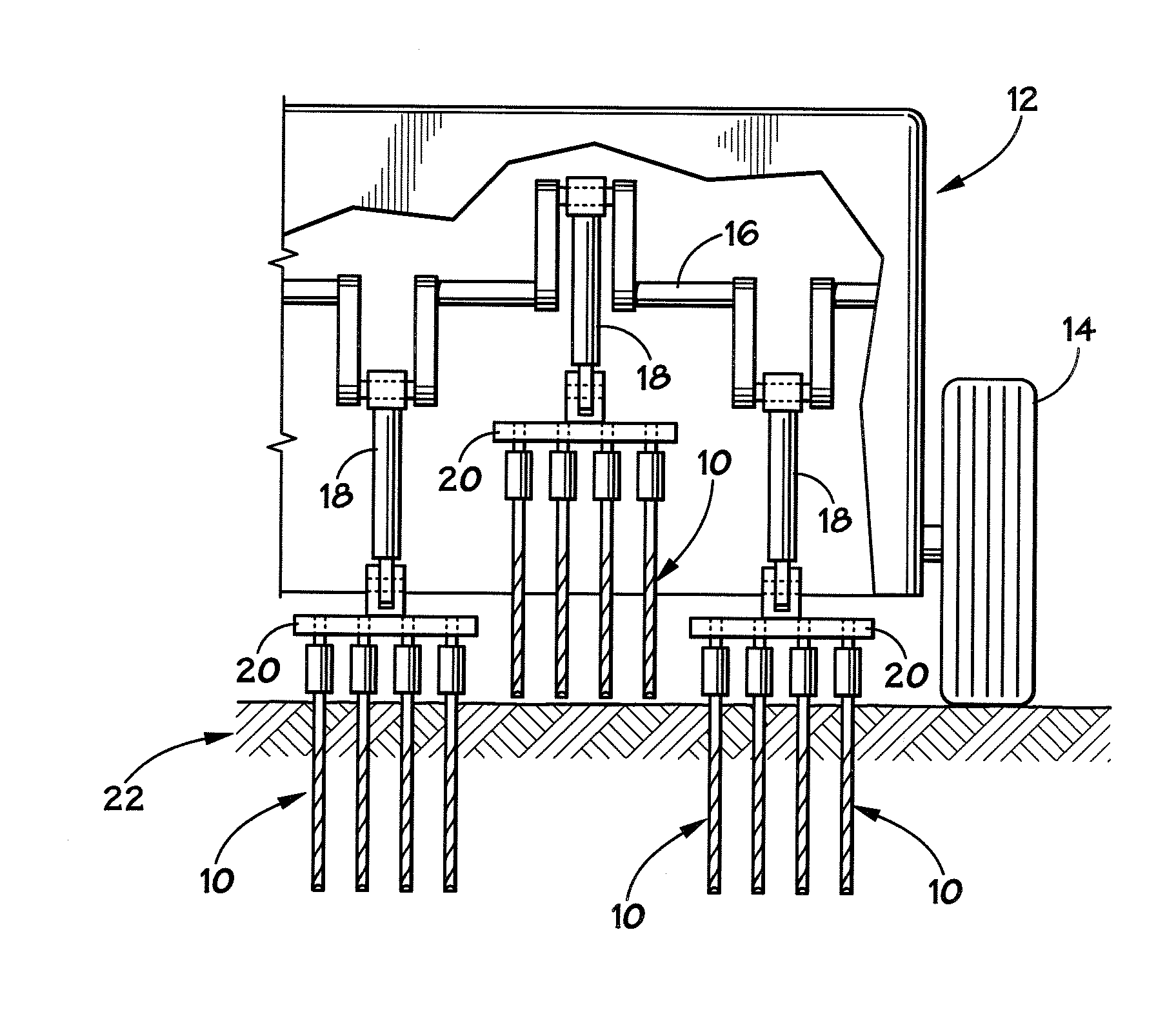
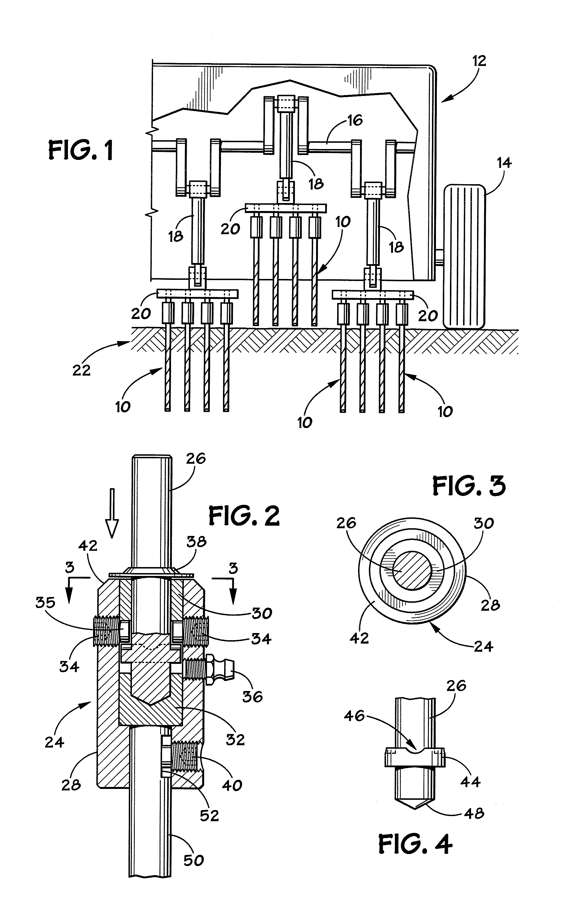
[0055] Referring now to FIG. 1, a portion of a reciprocating turf aerator is shown as a partial cut-away drawing. The aerator is shown in simplified form to illustrate how the turf drill of the present invention may be used in practice. Aerator 12 may be moved across an expanse of ground such as soil 22 on wheel(s) 14. Reciprocating heads 20 are connected to crankshaft 16 by connecting rods 18 which cause heads 20 to move generally up and down as crankshaft 16 rotates. Drills 10, attached to heads 20, are thereby alternately thrust into and withdrawn from soil 22. In some commercially-available aerators, crankshaft 16 is driven by the power take off (PTO) of a tractor used to pull aerator 12 across a putting green, for example.

[0056] As mentioned above, this is a simplified view of a reciprocating aerator. Commercial aerators ar...


PUM


Abstract

A novel drill for the aerification of turf grasses is disclosed. The drill comprises a chuck and a fluted turf drill bit held by the chuck. The chuck includes a locking mechanism which permits the chuck to rotate freely about its longitudinal axis when loaded in compression (as when the drill is inserted into the ground) but which locks, preventing rotation, when the drill is loaded in tension (such as when the drill is withdrawn from the soil). The drill bit has a smooth upper section and a fluted lower section. The smooth section decreases the probability of entangling the turf in the drill bit with subsequent lifting of the turf when the drill is withdrawn. The tip of the drill bit is adapted to provide a torque to the drill bit during insertion into the ground. Thus, the bit spirals into the ground upon insertion, but locks upon removal, thereby permitting the flutes of the bit to cut a cylindrical hole in the ground while removing soil from the hole by retaining it in the space between the flutes. The drill of the present invention may be used in aerators previously limited to solid or hollow-core tines.

Description

CROSS-REFERENCE TO RELATED APPLICATIONS [0001] This application is a continuation of U.S. patent application Ser. No. 10 / 527,611 filed Mar. 11, 2005, which is a continuation of United States Provisional Patent Application Ser. No. 60 / 450,847 filed Feb. 28, 2003, to which priority is claimed under 35 U.S.C. §120 and which is incorporated herein by reference in its entirety.BACKGROUND OF THE INVENTION [0002] 1. Field of the Invention [0003] This invention relates to soil aerification (or “aeration”). More particularly, it relates to a method and apparatus for the aerification of turf grasses using a self-rotating turf drill. [0004] 2. Description of the Related Art What is Aerification [0005] Aerification is a mechanical process that creates more air space in the soil and promotes deeper rooting, thus helping plants stay healthy. In most cases, this is achieved by removing cores (often called plugs) and then filling the holes with topdressing. Topdressing is often a certain grade of ...

Claims


Application Information

Patent Timeline
Patent Type & Authority Applications(United States)
IPC IPC(8): A01B45/02
CPCA01B45/023Y10T279/17017Y10T279/17821
Inventor FALTYSEK, DANIEL R.
Owner FALTYSEK DANIEL R
Why Eureka
Try Eureka