Prosthetic cardiac valve formed from pericardium material and methods of making same

a technology of pericardium and prosthesis, which is applied in the direction of prosthesis, blood vessels, cell components, etc., can solve the problems of stenosis and insufficiency, all the abnormal anatomy and function of the heart valve in a particular patient, and the need for emergency surgery, so as to prevent or minimize the leakage of the valve, prevent undesired abrasion, and facilitate the percutaneous insertion into the heart of a patient.

Active Publication Date: 2007-10-04
MEDTRONIC INC
View PDF99 Cites 533 Cited by
  • Summary
  • Abstract
  • Description
  • Claims
  • Application Information

AI Technical Summary

Benefits of technology

The present invention relates to an improved design for a prosthetic cardiac valve that uses a piece of pericardium material folded onto itself to form a unique valve shape. The valve has multiple arches and vertical segments that provide flexibility and durability. It can have up to three leaflets (tri-leaflet) or just two leaflets (bi-leaflet). A stented version of this valve allows it to be easily inserted through blood vessels into the heart. Overall, the new design provides better outcomes and reduced complications when replacing damaged natural cardiac valves.

Problems solved by technology

The technical problem addressed in this patent text relates to finding better ways to repair damaged or malfunctioning heart valves without causing complications like brain damage or strokes. Current methods of replacing heart valves often involve taking down the existing valve and putting in a new one, but this process poses risks to the patient and requires major surgeon y. Therefore, there is a need to create various valve assembly alternatives that can be tailored to meet the specific needs of different patients.

Method used


Image

  • Prosthetic cardiac valve formed from pericardium material and methods of making same
  • Prosthetic cardiac valve formed from pericardium material and methods of making same
  • Prosthetic cardiac valve formed from pericardium material and methods of making same

Examples


Embodiment Construction

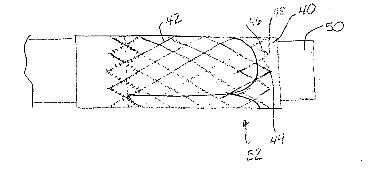
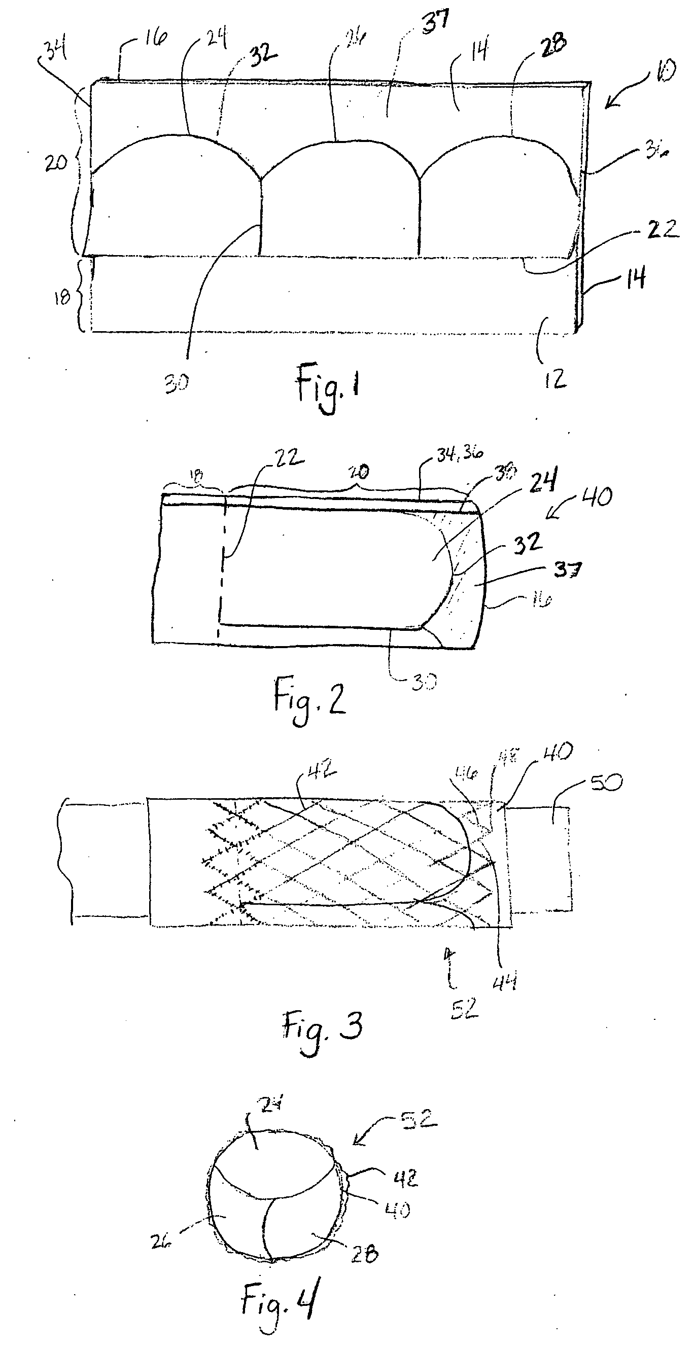
[0037]Referring now to the Figures, wherein the components are labeled with like numerals throughout the several Figures, and initially to FIG. 1, an intermediate configuration for preparing an exemplary pericardial valve in conjunction with the methods and valves of the present invention is illustrated. The pericardial valves of the invention can be used for replacement of pulmonary valves, aortic valves, mitral valves, or tricuspid valves, in accordance with the methods of the invention described herein. Alternatively, the valves of the invention can be used to replace a failed bioprosthesis, such as in the area of an aortic valve or mitral valve, for example. The shape, size, and configuration of the outer tubular portion of the pericardial valve can specifically be designed and chosen for the type of valve that is being produced. The valves of the invention can include stented or stentless valves, but in either case, the valves are compressible to a reduced diameter during the i...


PUM


Abstract

A prosthetic stented heart valve which includes a compressible and expandable stent structure having first and second opposite ends, an expanded outer periphery, and a compressed outer periphery that is at least slightly smaller than the expanded outer periphery when subjected to an external radial force. The valve further includes a valve segment comprising a dual-layer sheet formed into a generally tubular shape having at least one longitudinally extending seam, and a plurality of leaflets formed by attachment of an outer layer of the dual-layer sheet to an inner layer of the dual-layer sheet in a leaflet defining pattern. The valve segment is at least partially positioned within the stent structure. The valve may further include at least one opening in the outer layer of the dual-layer sheet that is spaced from both the first and second ends of the stent structure.

Description


Claims


Application Information

Patent Timeline
Owner MEDTRONIC INC
Why Eureka
Try Eureka