Dual-pump fluid distribution system for a hybrid electric vehicle

a hybrid electric vehicle and fluid distribution system technology, applied in the direction of positive displacement liquid engines, free piston pumps, hybrid vehicles, etc., can solve the problems of inability to meet such lubrication, cooling and pressure needs with an engine driven pump

Inactive Publication Date: 2007-10-18
GM GLOBAL TECH OPERATIONS LLC
View PDF4 Cites 56 Cited by
  • Summary
  • Abstract
  • Description
  • Claims
  • Application Information

AI Technical Summary

Problems solved by technology

When the engine is off or operating at low speeds; however, it may be impractical to meet such lubrication, cooling and pressure needs with an engine driven pump.

Method used


Image

  • Dual-pump fluid distribution system for a hybrid electric vehicle
  • Dual-pump fluid distribution system for a hybrid electric vehicle

Examples


Embodiment Construction

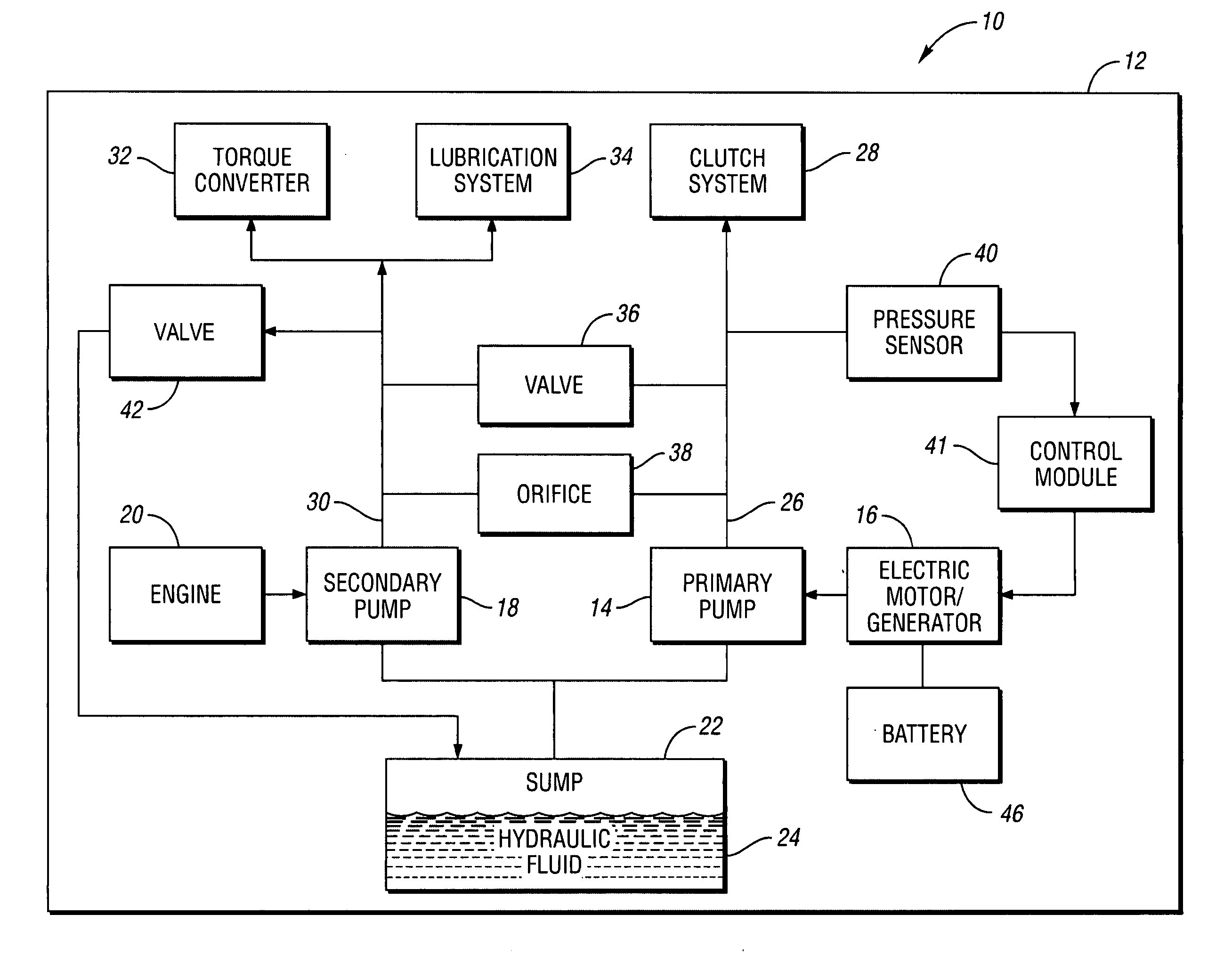
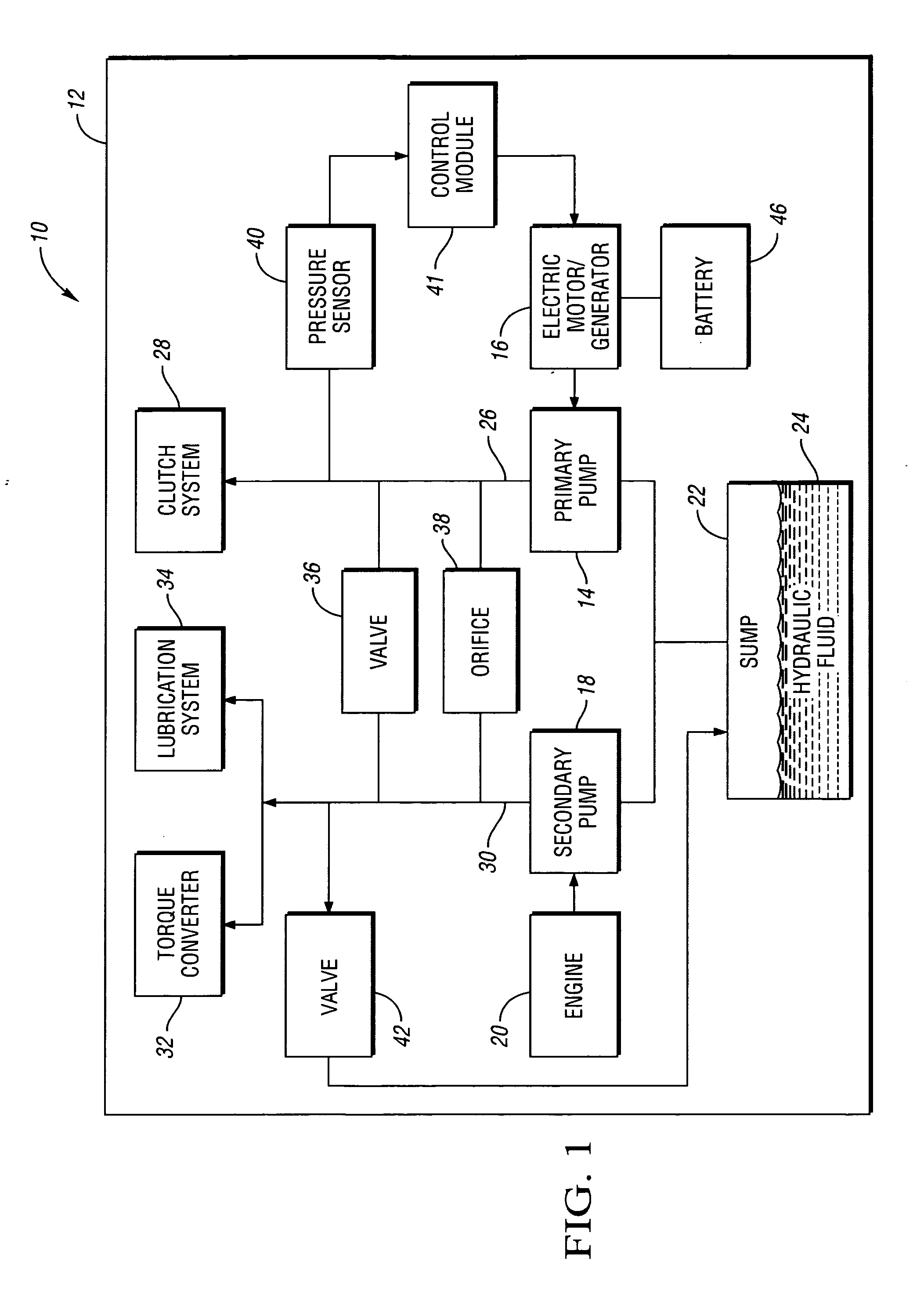
[0012] Referring to the drawings wherein like characters represent the same or corresponding parts through the several views, there is shown in FIG. 1 a schematic representation of a hybrid electric vehicle 10 having a dual-pump fluid distribution system 12. The fluid distribution system 12 is adapted to transfer fluid to one or more vehicle systems such as, for example, a clutch system 28 and a lubrication system or circuit 34. The fluid distribution system 12 includes a primary pump 14 operatively connected to and driven by an electric motor / generator 16. The fluid distribution system 12 also includes a secondary pump 18 operatively connected to and driven by an internal combustion engine 20. According to the preferred embodiment of the present invention, the pumps 14, 18 are fixed displacement pumps; however, alternate pump configurations may be envisioned as will be described in detail hereinafter.

[0013] The primary pump 14 draws hydraulic fluid 24 from a sump 22 and transfers ...


PUM


Abstract

The dual-pump fluid distribution system of the present invention preferably includes a sump having hydraulic fluid disposed therein. A first pump driven by an electric motor and a second pump driven by an engine are disposed in fluid communication with the sump. A plurality of vehicle systems are disposed in fluid communication with the first and second pumps. The first pump is configured to transfer hydraulic fluid to the vehicle systems when the engine is off. The first and second pumps are both configured to transfer hydraulic fluid to the vehicle systems when the engine speed is at or below a predetermined value. The second pump is configured to transfer hydraulic fluid to the vehicle systems when the engine speed exceeds the predetermined value. Accordingly, the hydraulic pressure needs of the vehicle systems are met for any given engine speed. A corresponding method in accordance with the present invention is similarly provided.

Description

TECHNICAL FIELD [0001] The present invention pertains generally to a dual-pump fluid distribution system for a hybrid electric vehicle. BACKGROUND OF THE INVENTION [0002] Conventional transmission pumps are driven by output from the engine for purposes such as meeting the cooling, lubrication and pressure needs of a transmission. When the engine is off or operating at low speeds; however, it may be impractical to meet such lubrication, cooling and pressure needs with an engine driven pump. Therefore, an additional pump driven by an electric motor may be implemented to provide lubrication, cooling and / or pressure when the engine is off or running at low speeds. SUMMARY OF THE INVENTION [0003] The dual-pump fluid distribution system of the present invention preferably includes a sump having hydraulic fluid disposed therein. A first pump driven by an electric motor and a second pump driven by an engine are disposed in fluid communication with the sump. A plurality of vehicle systems ar...

Claims


Application Information

Patent Timeline
Patent Type & Authority Applications(United States)
IPC IPC(8): B60K1/00F04B31/00B60K25/00
CPCB60K25/00B60W10/30B60W20/00F16H2061/0037F16H61/0025F16H61/0031F04B23/04B60W10/08B60W2050/004B60W2510/1075
Inventor CARLSON, RICHARD W.
Owner GM GLOBAL TECH OPERATIONS LLC
Why Eureka
Try Eureka