Instrument for endoscope

a technology of endoscope and endoscope, which is applied in the field of endoscope instruments, can solve the problems of increased size of damaged areas in the patient's body, difficult operation of treatment tools, and complicated treatmen

Inactive Publication Date: 2007-11-08
OLYMPUS CORP
View PDF30 Cites 39 Cited by
  • Summary
  • Abstract
  • Description
  • Claims
  • Application Information

AI Technical Summary

Problems solved by technology

Therefore, when an area to be treated is large or the position of the hole is inappropriate with respect to the part to be treated, the operation of the treatment tool may be difficult, or the treatment may be complicated.
In such a case, if another hole is provided at another position, the damaged area in the patient's body is increased in size.
When using such a treatment tool, it is difficult for the operator to intuitively know the position to be treated.
Additionally, a possible amount of offset between the treatment section and an inserted portion is restricted depending on the outer diameter of the hole provided in a body wall.
Therefore, it is difficult to perform wide area treatment with low damage.

Method used


Image

  • Instrument for endoscope
  • Instrument for endoscope
  • Instrument for endoscope

Examples


first embodiment

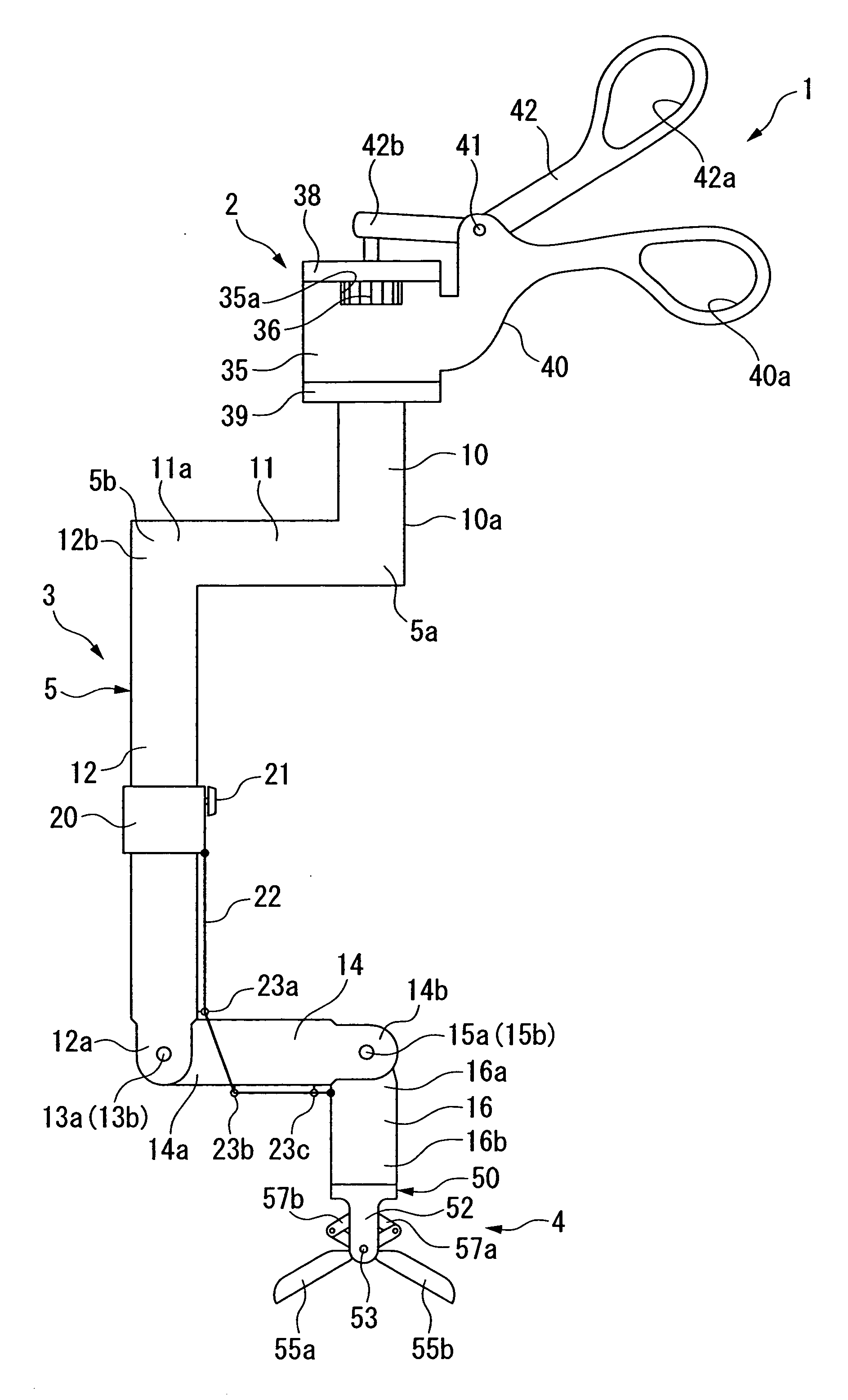
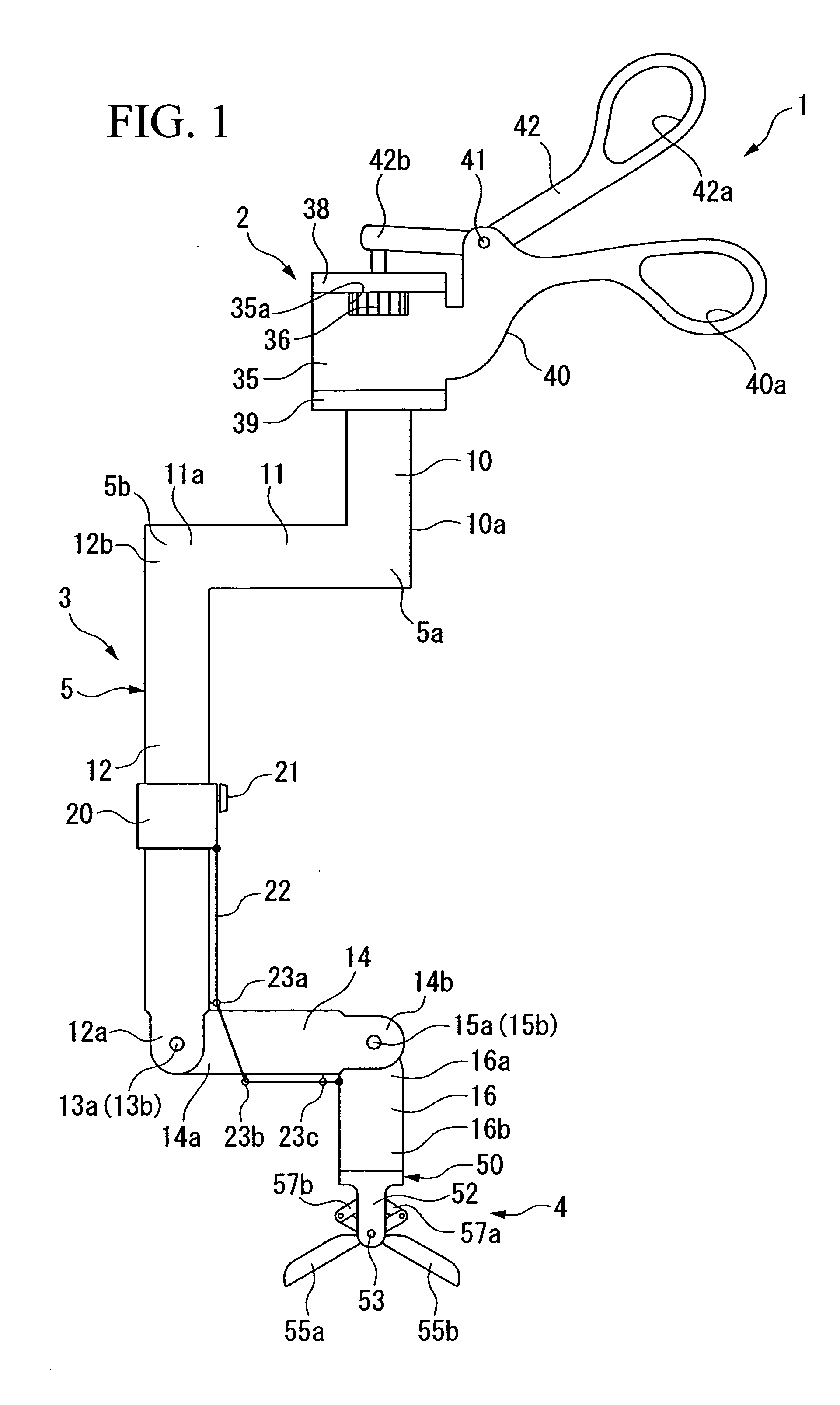
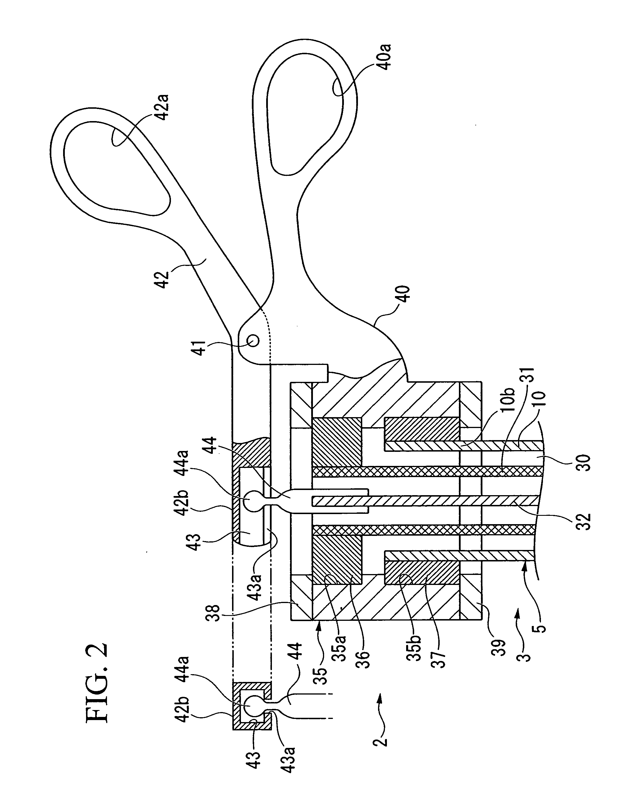
[0052]FIG. 1 shows a surgical treatment tool as a first embodiment of the instrument for the endoscope.

[0053] A surgical treatment tool 1 has an operation section 2 operated by an operator, an insertion section 3 which extends from the operation section 2, and a treatment section 4 provided at the head of the insertion section 3 so as to perform treatment on a living body.

[0054] The insertion section 3 has an outer pipe 5 formed by bending a metal pipe member having an outer diameter of 3 to 15 mm. The outer pipe 5 has a first insertion portion 10 connected to the operation section 2. The first insertion portion 10 extends along the axis of the operation section 2. A head portion 10a (a far end portion) of the first insertion portion 10 forms a first bent portion 5a which is substantially perpendicularly bent. From the first bent portion 5a, a first offset portion 11 extends in a direction perpendicular to the axis of the first insertion portion 10. A head portion 11a (a far end p...

second embodiment

[0073]FIG. 10 shows a surgical treatment tool as a second embodiment of the instrument for the endoscope.

[0074] In a surgical treatment tool 101, an insertion section 103 extends from an operation section 101, and a treatment section 104 is provided at the head of the insertion section 103.

[0075] As shown in FIGS. 10 and 11, the operation section 102 has a fixed handle member 105 and a movable handle member 106 which can slide along the fixed handle member 105 (in the longitudinal axial direction). The fixed handle member 105 has a ring 105a to be caught by a finger, at the base side of the fixed handle member 105. In an intermediate portion of the fixed handle member 105, a rail portion 105b is provided, which has a long hole formed along the length of the rail portion 105b. The movable handle member 106 slides along the rail portion 105b. As shown in FIG. 11, on a head side of the fixed handle member 105, a U-shaped groove 108 is provided for containing a coil 107 (i.e., a drivi...

third embodiment

[0098]FIG. 16 shows a surgical treatment tool as a third embodiment of the instrument for the endoscope.

[0099] A surgical treatment tool 201 has an insertion section 203 extending from the head of an operation section 202, and a treatment section 204 is provided at the head of the insertion section 203.

[0100] The insertion section 203 is made of a hollow pipe line 205 which is flexible and has an appropriate degree of hardness. A base end portion 205a (a near end) of the hollow pipe line 205 is connected to a side of a head portion 206a (a far end) of a handle-side housing 206 (as a first insertion portion) which is made of a rigid pipe member. In the handle-side housing 206, a communication passage 207 is provided, which is joined to the hollow pipe line 205. In addition, to the head portion 206a of the handle-side housing 206, a magnet 208 is fastened, which has a surface finished so that the surface can easily slide on a body wall W1.

[0101] A head portion 205b of the hollow pi...


PUM


Abstract

An instrument for an endoscope includes a first insertion portion having an base end to which an operation section is connected; a first offset portion extending outward from an axis of the first insertion portion; a second insertion portion having a base end joined to the first offset portion and an element extending parallel to the axis of the first insertion portion; a second offset portion which is joined to a head of the second insertion portion and reaches an extension of the axis of the first insertion portion; a third insertion portion which is joined to the second offset portion and has a portion arranged on an axis which is substantially the same as at least a part of the axis of the first insertion portion; and an inner hole formed through the first insertion portion, the first offset portion, the second insertion portion, the second offset portion, and the third insertion portion.

Description

[0001] This application is a continuation application in part based on U.S. patent application Ser. No. 11 / 237,479.BACKGROUND OF THE INVENTION [0002] 1. Field of the Invention [0003] The present invention relates to an instrument used together with an endoscope in a surgical operation using the endoscope. [0004] 2. Description of the Related Art [0005] In a surgical operation using an endoscope, treatment tools such as forceps are used. An example of the treatment tool is disclosed in U.S. Pat. No. 6,245,085. In an operation using such a treatment tool, a hole (called a “port”) having a diameter of 5 to 10 mm is provided in a body wall, and the treatment tool is inserted through the hole. In this case, the area where treatment is possible is narrower in comparison with an open operation in which a portion of a body wall is cut and opened. Therefore, when an area to be treated is large or the position of the hole is inappropriate with respect to the part to be treated, the operation ...

Claims


Application Information

Patent Timeline
Patent Type & Authority Applications(United States)
IPC IPC(8): A61B1/01
CPCA61B17/29A61B19/52A61B2017/00398A61B2017/00539A61B2017/00738A61B2017/2901A61B2019/5217A61B2017/2908A61B2017/291A61B2017/2927A61B2017/2929A61B2019/5206A61B2017/2902A61B90/36A61B2090/3614A61B2090/306
Inventor MIYAMOTO, MANABUDEJIMA, TAKUMIMINOSAWA, RYOMATSUNO, KIYOTAKAHASHIMOTO, TATSUTOSHI
Owner OLYMPUS CORP
Why Eureka
Try Eureka