Stapler for endoscopes

a technology for endoscopes and staples, which is applied in the direction of surgical staples, oesophagoscopes, surgical forceps, etc., can solve the problems of difficult and time-consuming work, requiring a great deal of skill to manipulate tissues and stapling devices, and it is impossible to hold the aforementioned parts rigidly together

Inactive Publication Date: 2005-03-29
GERD IP INC
View PDF31 Cites 1755 Cited by
  • Summary
  • Abstract
  • Description
  • Claims
  • Application Information

AI Technical Summary

Benefits of technology

In a preferred embodiment of the invention, there are either two or three arrays of staples and there are five staples in each array. Of course other arrangements with a different number of arrays and / or of staples can be provided. Windows are preferably provided on each side of the staple cartridge, to assist in locking it in place after indexing.

Problems solved by technology

Most of these are very difficult and time consuming to work with, requiring a great deal of skill to manipulate the tissues and the stapling device.
Consequently, at the time the staples are fired, the anvil and the head must be clamped rigidly together, or the force will cause them to separate, and the staples will not fully bend.
With current stapling methods, it is impossible to hold the aforementioned parts rigidly together unless they are rigidly or pivotally connected at the time of placement.
Because of the need to hold the anvil part and the staple dispensing part of the stapler together, a totally flexible connection is not practical, using existing methods.

Method used


Image

  • Stapler for endoscopes
  • Stapler for endoscopes
  • Stapler for endoscopes

Examples


Embodiment Construction

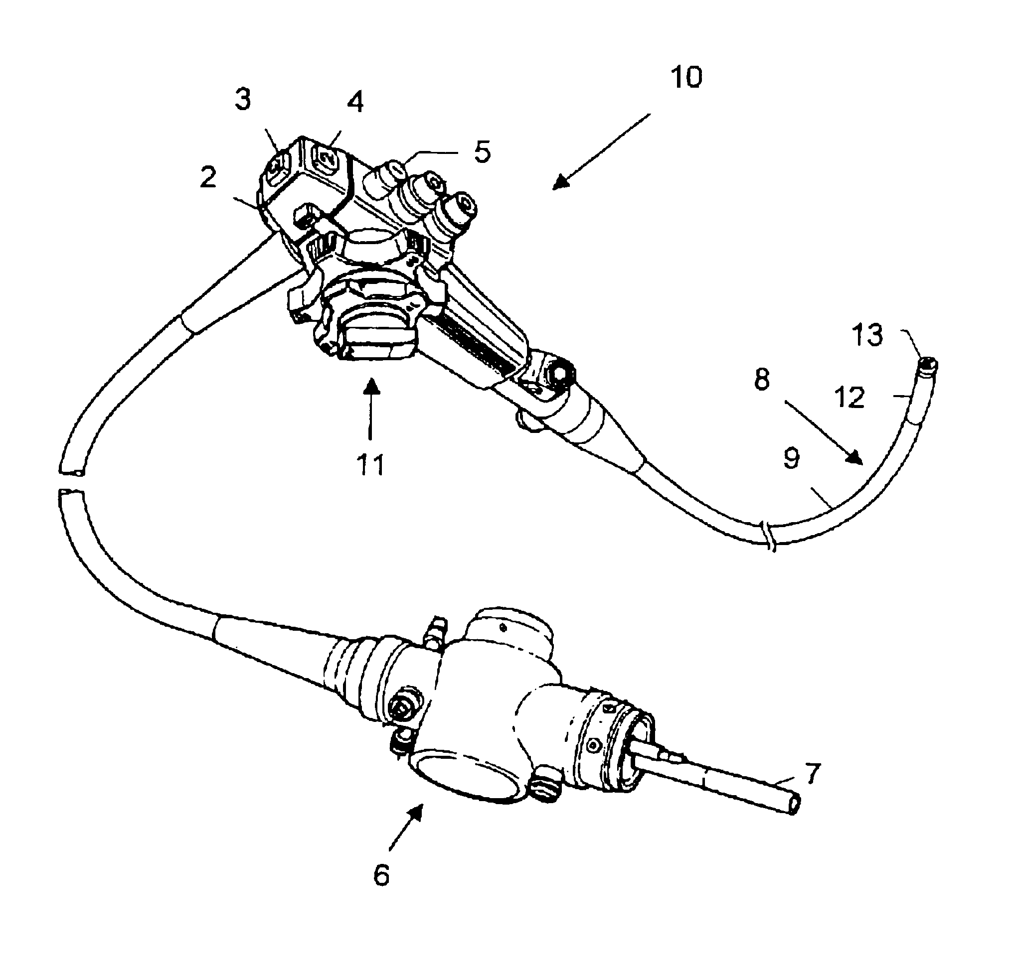
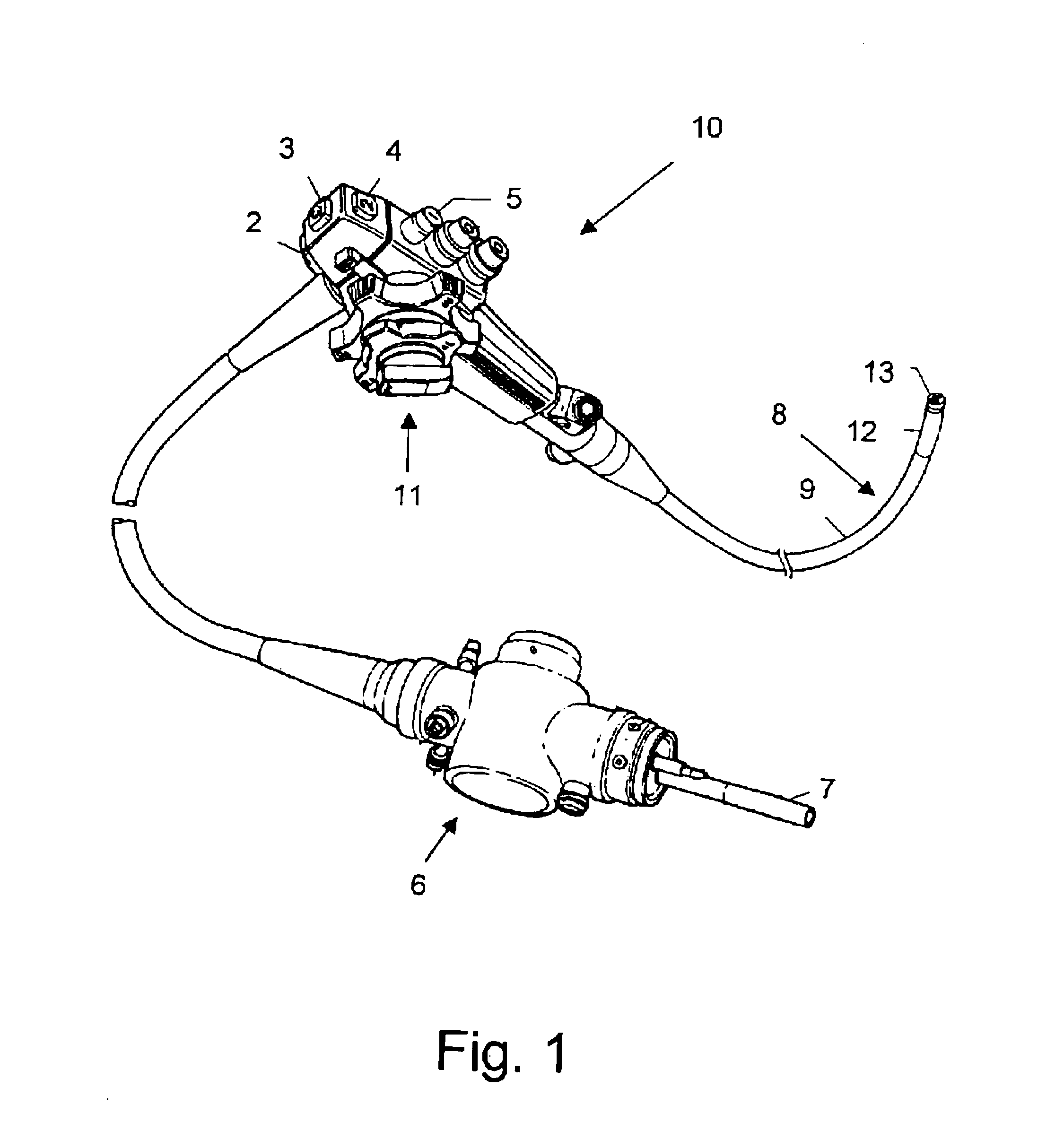
The invention will now be further explained through the illustrative and non-limitative description of preferred embodiments. A conventional endoscope is illustrated in FIG. 1. This endoscope comprises several features, such as the operating switches, the angulation lock, etc., that may be present in the device of the invention, but that will not be described in detail in the description to follow, because they are conventional and well known to the skilled person. Thus, in the following description only elements needed to illustrate the invention will be described. Briefly, however, the endoscope illustrated in FIG. 1 and generally indicated at 10, is provided with a control section 11 provided with suction valves, locks, switches, etc., switches 2-5 being marked for illustration purposes. It also comprises a connector section 6, used to connect air and water inlets, light guides, etc., the light guide being indicated at 7, for illustration purposes. The insertion tube 8 consists o...


PUM

PropertyMeasurementUnit
distanceaaaaaaaaaa
flexibleaaaaaaaaaa
magnetic fieldaaaaaaaaaa

Abstract

A stapling device for a surgical endoscopic device provided with at least one flexible portion, comprising a staple-firing portion and an anvil portion, wherein one of the staple firing portions and one of the anvil portions are located longitudinally displaced from one another along the longitudinal axis of the endoscopic device, with at least a part of said flexible portion between them. The parts of the stapling device are in correct working relationship when one or more alignment and / or locking pins or screws that are stored in one of the staple firing portions or one of the anvil portions are extended and engage and lock or screw into receptacles that have been provided on the other of the staple firing portion or of the anvil portion.

Description

FIELD OF THE INVENTIONThe present invention relates to endoscopic apparatus. More particularly, the invention relates to a stapler which is part of an apparatus and a method for using this apparatus to perform endoscopic surgical procedures.BACKGROUND OF THE INVENTIONIn recent fears, surgeons have been increasingly using surgical staples instead of conventional sutures. Surgical staples and surgical stapling instruments have made many difficult procedures much simpler to perform, and significantly reduced the time required to perform them, thus allowing the patient to spend less time under general anesthesia.In general, modern surgical stapling instruments for use on internal organs and tissues are comprised of a head containing a cartridge which holds the staples and a mechanism for ejecting the staples out of the cartridge, either sequentially or simultaneously, and driving them through the tissue. Typically, on the other side of the tissues to be stapled there is an anvil, which ...

Claims


Application Information

Patent Timeline
Patent Type & Authority Patents(United States)
IPC IPC(8): A61B1/00A61B1/005A61B1/273A61B17/068A61B17/28A61B17/00A61B17/10
CPCA61B1/0005A61B1/00193A61B1/0051A61B1/0055A61B1/2736A61B17/068A61B17/0686A61B17/072A61B1/00181A61B2017/2905A61B2017/00022A61B2017/00292A61B2017/003A61B2017/00314A61B2017/00827A61B2017/07214
Inventor SONNENSCHEIN, ELAZARSONNENSCHEIN, MINELUCRAINICH, LAWRENCE
Owner GERD IP INC
Why Eureka
Try Eureka